4.4.2 Additional views, profile and cross-section
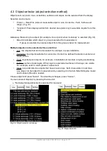
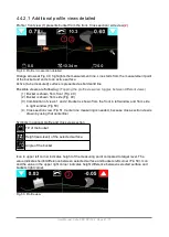
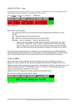
Additional views can be added onto the display (Fig. 48):
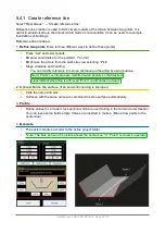
To add profile view, select:
•
“
Options
”
◦
“Profile / crossection”
•
“Enabled” (Profile view(s) are visible / hidden)
•
“Cut inactive layers” (Show all surfaces on the profile view)
•
“Show zoom controls” (Zoom control icons are visible)
•
“Cut lines / pipes” (Cut line and pipes are indicated with 'X')
•
“Bucket angles” (angles of two axes are displayed in
additional profile views)
•
“Model Z” (Z value is shown)
•
Breaklines for active DTM
•
Bucket arrow indicators
To insert more information to the profile view, select
:
•
“
Options
”
◦
“Misc GUI items”
•
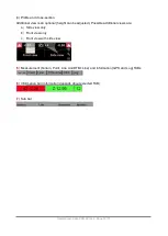
“Model offset”. Height offset of model is shown. Change with double tapping the
value on screen. (Fig 47)
•
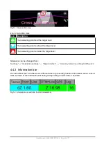
“Measuring point coordinates” (X, Y and Z coordinates of the bucket measuring
point are shown on the screen Fig. 46)
•
Positioning on/off button
•
Line guidance indicator
Fig. 48. Profile / crossection
User Manual. Xsite PRO SPI 14.2 Page 40 / 77
Fig
.
46. Measuring point offsets
Fig
.
47. “Model offset” value
Summary of Contents for XSITE PRO SPI 14.2
Page 1: ...XSITE PRO SPI 14 2 USER MANUAL Version 1 14 2 46 October 2018...
Page 33: ...Fig 36 Tilt bucket calibration User Manual Xsite PRO SPI 14 2 Page 30 77...
Page 76: ...User Manual Xsite PRO SPI 14 2 Page 73 77...
Page 77: ...User Manual Xsite PRO SPI 14 2 Page 74 77...


