background image

4   WORKING USING POSITIONING (3D / LANDNOVA)

When using the positioning (using the 3D):

GNSS receiver with antennas are needed

RTK correction is needed.

3D project have to be imported.

The coordinates of the bucket are known. The machine can be moved in the jobsite without
the need for physical reference points or lasers.

Benefit

: Physical reference points or laser transmitter are not needed.

Press “3D” icon from the Vision to start LandNova.

Hint!  LandNova can be auto started by selecting “Autostart LandNova”:

Start screen → Settings → GPS Settings → “Autostart LandNova” (Code required, contact local 
dealer)

Before starting work, the operator must check accuracy of the system. The following points have a 
significant impact on quality and accuracy of work. Procedures in the Table 2 have to be carried 
out.

Table 2. Procedures before working

Action

Description

RTK correction 
connection

Establish a connection to a base station or a base station network. SIM 
card (or alternatively UHF radio) is needed for receiving RTK correction.

Coordinate system 
selection

Select the correct coordinate system and make sure that the coordinate 
offsets are correct

Geoid selection

Select the correct Geoid Model or alternatively, adjust the Z coordinate 
offset

GNSS accuracy test

Check the accuracy of the system on known calibration point(s).

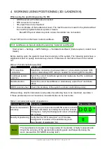
While working, direction calculation and quality of positioning have to be monitored, see table 3. 
If these parameters are not monitored, measurements can be inaccurate.

Table 3. Accuracy and quality of positioning

Accuracy / quality

Description

View on status bar

Direction calculation 
accuracy

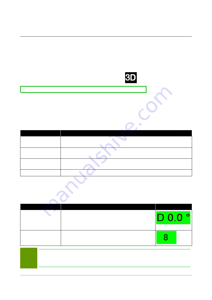
When using a single antenna GNSS system, activate
direction calculation by rotating the machine at least 
90 degrees. Verify that background colour of heading
(

D

) is green

Quality of positioning Verify that the “RTK correction” is in FIX state, 

background of number of the satellites is green. 
See “Quality of positioning” 6.4

Note!

The manufacturer or dealer is not responsible for inaccurate or faulty measurements.
Check the accuracy of the system before starting work and frequently during the 
work  (see section 6.8 'GNSS accuracy test').


User Manual. Xsite PRO SPI 14.2  Page 31 / 77

Summary of Contents for XSITE PRO SPI 14.2

Page 1: ...XSITE PRO SPI 14 2 USER MANUAL Version 1 14 2 46 October 2018...

Page 2: ...e slope using the system 21 3 8 Working with a Laser reference with or without the stake 22 3 8 1 Automatic height update to a laser reference while working 24 3 9 Special settings 25 3 9 1 Alert limi...

Page 3: ...Additional files for digital terrain models and line models 62 5 5 2 1 Point files 62 6 ACCURACY TEST 63 6 1 Depth and distance accuracy test 1 63 6 2 Depth and distance accuracy test 2 63 6 3 Tilting...

Page 4: ...Non observance of the User Manual Non intended and improper use Use beyond operation limits Use by insufficiently qualified and trained personnel Use of unauthorized spare parts and accessories Decons...

Page 5: ...nd guidelines given here is important for safe operation Therefore this operator Manual must be read prior to any use of the product and applied without fail by any person assigned with working proces...

Page 6: ...ully to prevent accidents personal injury and material damage Indicates a hazardous situation If not avoided could result in death serious injury or material damages Note Emphasizes useful tips and re...

Page 7: ...tuations without any limitations are considered improper use of the product Non conventional use Exceeding the limit values given in the manual Use of the product without instructions Use of the produ...

Page 8: ...ly studying and understanding the manuals for the product s operation The operator informs the manufacturer or the authorized dealer without any delay if any safety defects occur at the product or dur...

Page 9: ...as the current road traffic regulations Risks caused by faulty measurement results Faulty measurement results due to use of a dropped product another illegitimate demand or an alteration can lead to...

Page 10: ...dures for alerting the emergency services Keep access routes clear for emergency vehicles In the event of an accident proceed appropriately Shut down the equipment immediately by switching the power o...

Page 11: ...tal not vertical plumbline calibration The system contains the following components by default Computer unit MCC15 Display unit Xsite PRO display Gravitation sensors G2 sensors Number of sensors depen...

Page 12: ...cated inside of the MCC 15 computer unit 1 4 Transportation and storage When transporting the equipment to the usage site or carrying it in the field always ensure that the product is transported in s...

Page 13: ...e sure to visually check that the cable is properly connected An improper connection may cause damage to the display unit or to the computer The cable must not be connected or disconnected while the s...

Page 14: ...ne is used below 0 C 32F temperatures it will take time for the sensors to warm up and provide accurate results The recommended amount of time needed between turning the system ON and starting work is...

Page 15: ...stem can be turned off by pressing from start window If you need to continue working with 2D application the LandNova can be closed by selecting Project Back to 2D or Exit If a shut down cannot be car...

Page 16: ...utton 1 Selections from the Main menu of the Vision fig 8 1 Start opens 2D work view as seen in the fig 7 Measurement work view 2 Language opens language selection Language of 2D software user interfa...

Page 17: ...ange bucket by clicking B1 B10 Side view of the bucket The view from the side of the bucket Zoom in out by using the and icons Front view of the bucket The view from the front of the bucket Zoom in ou...

Page 18: ...anced in fig 9 Sets the depth reading and bucket tip to the start of the slope Slope and depth values have to be defined before starting work Profile is visualized on display See fig 11 red line More...

Page 19: ...istance Set start distance See section Distance settings 3 5 Slope settings 5 Set slopes See section Slope measurement Movement limits 6 Set limits Warning levels can be set The system will alert the...

Page 20: ...w circle fig 14 will reset both depth and distance to predefined values 5 Verify that start depth is 30 meter reading inside the green circle at the Fig 14 6 Start and continue excavating until bucket...

Page 21: ...distance to predefined values 4 Verify that the starting distance is zero or entered distance value when bucket is at the stake zero in this example 5 Start and continue working until distance is reac...

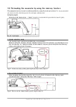
Page 22: ...m a new location Before moving the machine choose a stable memory point For example a good reference is a big rock see fig 21 Bring the blade of the bucket to a memory point and press the Memory butto...

Page 23: ...ference point stake even though machine position and altitude has been changed see fig 23 Fig 23 Digging continues after relocating the machine Warning Every relocation of the machine degrade the prec...

Page 24: ...only one direction so Y is set to zero Return to the work view It is recommended to use free view mode marked with green circle below Fig 24b Press Start slope Fig 24 Advanced slope tool setting value...

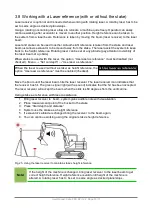
Page 25: ...the laser is used without a stake as height reference the option Use laser as reference must be enabled checked Move the boom until the laser beam hits the laser receiver The laser receiver icon indi...

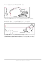
Page 26: ...om a stake or from another reference If excavator s altitude is changed bring the receiver to the beam again Fig 27 Move the boom to the laser beam until audible note is given In this example the targ...

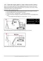
Page 27: ...r Set laser start depth same as jobsite laser height in this example 90 0 metres 2 Enter Set target depth in this example 87 0 metres 3 Select tick Menu Set target depth Use laser as reference 4 Conti...

Page 28: ...l levels Level1 defines tolerance for Ongrade so there is the same tolerance below grade and above grade Colour of the XD2 level indicator Fig 31 Colour Height Tolerance settings see Fig 30 Yellow Abo...

Page 29: ...tton 1 2 3 or 5 The system measures height and distance of boom pins not from the highest point of the boom The system does not prevent the movement it only gives a warning Fig 32 Warning limits for b...

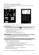
Page 30: ...n of the dipper stick 8 Turn the bucket slowly towards the plumb line until it barely touches the line 9 Press Calibrate plumbline If rotator or tilting unit is installed calibration is needed Usually...

Page 31: ...height and distance readings 3 Turn the bucket without tilting it sideways to a different position from position A to position B and keep bucket s measurement point on the same point 4 Verify that the...

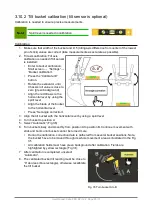
Page 32: ...ign the blade of the bucket to the horizontal level Press Set angle correction 3 Align the tilt bucket with the horizontal level by using a spirit level 4 Turn bucket to position A 5 Select Automatic...

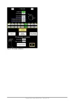
Page 33: ...Fig 36 Tilt bucket calibration User Manual Xsite PRO SPI 14 2 Page 30 77...

Page 34: ...receiving RTK correction Coordinate system selection Select the correct coordinate system and make sure that the coordinate offsets are correct Geoid selection Select the correct Geoid Model or alter...

Page 35: ...oject have to be opened Project can be imported to the system from USB memory stick FTP or using third party services like Infrakit Select Project Import from FTP USB How to open a project 1 Open proj...

Page 36: ...can be measured for example in pipe installation Centerline line objects suitable for center line Center line defines the station number and cross section Point imported point objects for example in i...

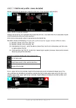
Page 37: ...va with profile and cross view sections 1 Drop down menu Features are available from the drop down menu see section 5 1 Menu structure 2 View icons and measuring point selection Operator can change to...

Page 38: ...Possible additional views are a Side view only b Front view only c Front view with side view 5 Measurement Terrain Point Line And DTM Line and information GPS and Log TABs 6 Information bar informati...

Page 39: ...ent point can be seen from the bucket icon Fig 40 The measurement point can be changed toggled by touching the bucket icon Left Center Right Automatic How to center the machine or a map Press View ico...

Page 40: ...he map can be done by swipe action Zoom controls and are available in all views highlighted by yellow circles in Fig 42 and 43 Fig 42 Map view Top view icon is circled by green top view according to a...

Page 41: ...bin view 3D view It is possible to view 3D map from a chosen direction by selecting 3D map by pressing the icon marked by green circle in Fig 45 The point of view can be changed with a swiping action...

Page 42: ...iangle below the icon shows the measurement point When automatic measurement point is selected The system selects the lowest point of the bucket blade as the measuring point When the bucket blade is t...

Page 43: ...two axes are displayed in additional profile views Model Z Z value is shown Breaklines for active DTM Bucket arrow indicators To insert more information to the profile view select Options Misc GUI ite...

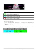
Page 44: ...ation of views 1 and 2 Bucket is shown from the front in left window and from side in right window Fig 50 4 Cross section view Fig 51 Center line measuring is needed because cross section view is draw...

Page 45: ...rance can be changed from Settings Installation settings User Interface Accuracy tolerances Height difference 4 4 3 Information bar The information bar is divided to six different tabs for presenting...

Page 46: ...e height Z Number of satellites which are used to positioning with RTK correction Shows the count of available satellites The background colour indicates the state of the RTK correction For best accur...

Page 47: ...ows the distance between the selected point and the measuring point in boom line direction dS distance see the Fig 55 Shows the distance between the selected point and the measuring point against boom...

Page 48: ...S distance Distance from the measuring point to the selected line object Fig 57 Measuring point Orange arrow points the circle that indicates the measuring point of the line Name of the line is shown...

Page 49: ...ground colour of the field indicates the state of the RTK correction State have to be FIX field is green for most accurate work More information about accuracy is in section GNSS accuracy test Satelli...

Page 50: ...uilt data can also be stored by pressing the satellite count number As built points are always stored to current layer For example if you are working with DTM model and the selected surface name is Fi...

Page 51: ...n from the positioning device Positioning device coordinates positioning antenna are read by pressing the Get from the Receiver Point is stored with current code by pressing Save point Enter Code Name...

Page 52: ...w metres Codelist Codes are used to identify objects such as lightpoles pipes and points Fig 63 Numeric codes in the left column are translated to text form at the right column Fig 63 Feature Codelist...

Page 53: ...Collected Points Logged objects are exported to Project or to USB memory stick or by FTP upload Undo last log point Last log point is deleted Project changelog Project changelog can be used to synchro...

Page 54: ...e DTM Bucket arrow indicators Misc GUI items Model offset Measuring point coordinates Positioning button ON OFF button is visible or hidden Line guidance indicator Logging Require shift height System...

Page 55: ...uage FCL User Interface LibConverter config Show Antenna For service personnel only Show status Status of GPS and COM ports Geoid Model global coordinate system Open ini file For service personnel onl...

Page 56: ...n autosnap mode is calculated in XY Active point switch threshold How many percent closer a new object needs to be before autosnap function is changing to nearest object 0 is the default Installation...

Page 57: ...odify reference line slope distance and heading by using buttons Note Point2 coordinates are modified automatically so that desired slope distance heading is achieved Point1 coordinates are fixed 2 Op...

Page 58: ...metres d Column spacing in metres 3 Place bucket s measurement point to the starting point 1 of the field and press Start Point 4 Place bucket s measurement point to the direction point 2 of the fiel...

Page 59: ...ing the name or the stage of the project Control keys for desktop Landnova A D Rotate machine on the map W S Drive machine on the map R F Up Down Z axis height Keeping the Shift pressed with W S A D t...

Page 60: ...n the screen 5 After a successful download the project is automatically taken in use 5 4 5 Importing the project from USB memory stick Note Note that all the files need to be in a folder on USB memory...

Page 61: ...3DFACE objects from CAD In LandXML format DTM TIN should be a surface object How different layers are shown on the display Multiple files in DXF or LandXML format can be imported to single project fol...

Page 62: ...to it Background maps can be used with DXF and LandXML files When BG is added to the file name all measuring functions are disabled and handling of the background map is much faster For example rename...

Page 63: ...lines for pipes Using different colours and descriptive naming to separate lines Both functions above the measurement tab s are the same dZ Height difference between the bucket s measuring point and...

Page 64: ...f the object If the Z coordinate is zero then the functionality is automatically in 2D mode With 3D objects the alarm can be used for avoiding damaging existing pipes or cables for example Fig 70 disp...

Page 65: ...ting the position of a simple object for example a well or a lamp post Points can be imported as DXF LandXML PXY GT and KOF formats When importing points coding can be used to differentiate points fro...

Page 66: ...Turn the bucket without tilting it sideways to a different position and place it on the same point 3 The height and lengthwise distance readings should be close to zero in every position an accuracy t...

Page 67: ...f the bucket to the reference point Zero the measurement readings 4 Tilt the bucket and put the left corner on the reference point 5 Height and lengthwise distance readings should be as close to 0 00...

Page 68: ...tellites from the view of the observer Positioning is more accurate if satellites are widely and evenly spaced throughout the sky Baseline Increasing the distance between the machine and the base stat...

Page 69: ...gle Fig 75 FIX The background of available satellites and sea level indicators are yellow accuracy is not acceptable HDop value is outside a predefined value User Manual Xsite PRO SPI 14 2 Page 66 77...

Page 70: ...your local policy for radio equipment The Internet When using the Internet for streaming the correction data the operating radius of a base station can be extended up to 30 km However the longer the...

Page 71: ...re projected from an ellipsoid onto a plane A Cartesian coordinate system specifies a position by using metric units instead of angles The coordinates that specify a point on a plane are typically cal...

Page 72: ...the machine Note If the checkpoint is measured with the GNSS receiver of the machine only calibration of the machine can be verified A checkpoint measured by a surveyor is needed for verification of...

Page 73: ...lay unit simultaneously then remote connection opens and Headset icon appear on the screen Double clicking the Headset icon and selecting Cancel help request will close the connection Closing the menu...

Page 74: ...perating temperature 20 to 50 C Dimensions 250 x 160 x 90 mm Weight 2 5 kg Connections CAN CAN XD2 LED display Display Xsite Pro 3x USB 2 0 5x RS232 2x GSM antenna SIM CFast DisplayPort Ethernet PWR X...

Page 75: ...n 2 5 W IP classification IP67 Operating temperature 20 to 60 C Dimensions 315 x 96 x 55 mm Weight 0 7 kg I O CAN RS 232 Compatible lasers All rotating lasers with visible or infra red light wavelengt...

Page 76: ...User Manual Xsite PRO SPI 14 2 Page 73 77...

Page 77: ...User Manual Xsite PRO SPI 14 2 Page 74 77...

Page 78: ...User Manual Xsite PRO SPI 14 2 Page 75 77...

Page 79: ...User Manual Xsite PRO SPI 14 2 Page 76 77...

Reviews: