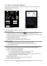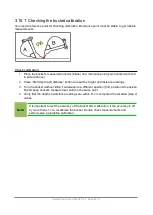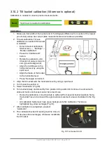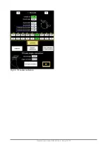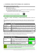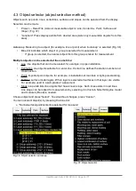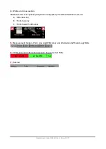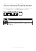
4.4.2.1 Additional profile views detailed
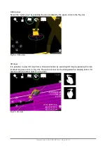
Profile / front view
(1)
presents bucket from the front. Cross section / side view
(2)
Fig. 49. Profile / crossection detailed.
Orange arrows at Fig. 49 highlights the measurement line. Line starts from the measurement point
of the bucket and ends to an active surface.
Active (to be measured) surface is presented as bold solid line.
Possible views are following:
(Tapping the profile view area toggles between different views)
(1) Bucket is shown from front (Fig. 49 )
(2) Bucket is shown from side (Fig. 49 )
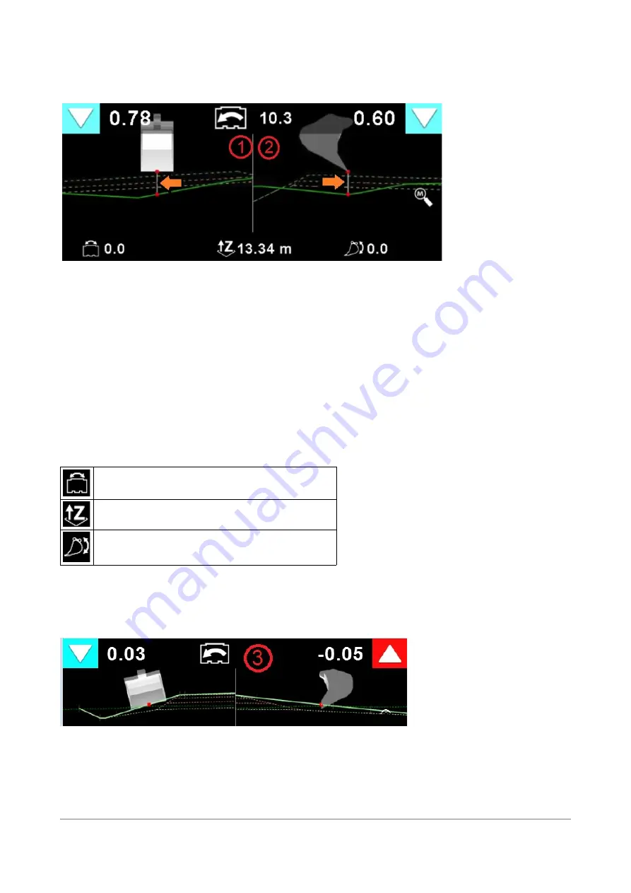
(3) Combination of views 1 and 2. Bucket is shown from the front in left window and from side
in right window (Fig 50)
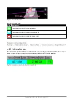
(4) Cross section view (Fig 51. Center line measuring is needed, because cross-section view is
drawn by using that centerline)
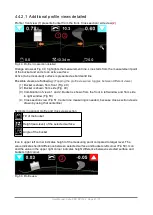
Symbols in optional profile and cross view section
Tilt of the bucket
Height (sea-level) of the selected surface.
Angle of the bucket
Icon in upper left corner indicates height of the measuring point compared to target level. The
value indicates height difference between selected surface and buckets left corner (Fig 50). Icon
and the value in the upper right corner indicates height difference between selected surface and
buckets right corner.
Fig. 50. Profile view
User Manual. Xsite PRO SPI 14.2 Page 41 / 77
Summary of Contents for XSITE PRO SPI 14.2
Page 1: ...XSITE PRO SPI 14 2 USER MANUAL Version 1 14 2 46 October 2018...
Page 33: ...Fig 36 Tilt bucket calibration User Manual Xsite PRO SPI 14 2 Page 30 77...
Page 76: ...User Manual Xsite PRO SPI 14 2 Page 73 77...
Page 77: ...User Manual Xsite PRO SPI 14 2 Page 74 77...

