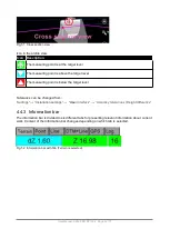
4.4.3.1
Terrain
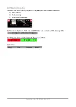
Height difference to the selected surface and height of the sea-level are shown
.
Gives
useful
information when working with digital terrain models (DTM).
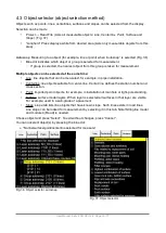
Fig. 53. Terrain tab
dZ height difference
Difference between a selected DTM and the measuring point of bucket.
Background colour in the “
dZ
” field indicates height offset of the measurement point.
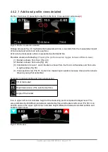
Blue
Bucket is above the target level
Green
At the target level within set tolerance.
“Settings
” → ”
Installation settings
” → “User
Interface
” → “
Accuracy tolerances
/
Height difference
”.
Red
Bucket is below the target level
Z height
(absolute height, height from the sea-level)
•
Field indicates absolute height
Z
.
Number of satellites which are used to positioning with RTK correction.
•
Shows the count of available satellites. The background colour indicates the state of the
RTK correction. For best accuracy this must be in the FIX state (see Quality of positioning –
FIX, FLOAT and SPS states).
•
For some GNSS receivers GPS and GLONASS satellites are separated, for example “12 +
6”. In that case the overall number of satellites is 18.
•
“As-built” data point is stored by pressing the satellite count panel (Fig.53, red circle).
“As-built” points are always stored to the current layer. For example, if you are working with the
DTM model and the model / layer name is the "Final surface" then all points are stored to the “Final
surface” layer. This can also be seen in the “as-built” data file when it is exported from the system.
User Manual. Xsite PRO SPI 14.2 Page 43 / 77
Summary of Contents for XSITE PRO SPI 14.2
Page 1: ...XSITE PRO SPI 14 2 USER MANUAL Version 1 14 2 46 October 2018...
Page 33: ...Fig 36 Tilt bucket calibration User Manual Xsite PRO SPI 14 2 Page 30 77...
Page 76: ...User Manual Xsite PRO SPI 14 2 Page 73 77...
Page 77: ...User Manual Xsite PRO SPI 14 2 Page 74 77...

