32 - EN
These assembly, operation and maintenance instructions must be kept for the entire period of use!
4
Mounting
4.1
Safety information for installation and
assembly
WARNING
Danger of poisoning from harmful
fumes when welding galvanised or
painted components!
When welding galvanised or painted
components, fumes emerge that will
lead to health impairments when being
inhaled.
•
In order to avoid the production of
fumes, sand off the paint and, if
present, also the zinc layer on the
areas to be welded.
•
Installation work may only be carried out by
specialist staff.
•
Read these installation instructions before you
start installing the product.
•
Never carry out the installation on your own.
Some of the work steps can only be achieved
with two people working.
4.2
Scope of delivery
The scope of delivery comprises:
•
Dock leveller with pre-assembled components
– Hydraulic unit
– 4 transport lugs
•
Assembly and operating instructions
•
Cardboard box with:
– Control unit including cabling
– Assembly and operating instructions of the
control unit
– Short operating manual
– Cable clamps
– Sealing plugs
•
Touch-up paint (if applicable)
4.3
Mounting requirements
4.3.1 Preparation (not included in the scope of
delivery)
Before carrying out any installation work, make sure
that the following requirements are met:
For all installation conditions:
•
The dimensions of the installation point
correspond to the specifications in the installation
drawing.
– Length and width
– Height (front and rear side)
– Perpendicularity (difference in length of the
diagonals max. 10 mm)
•
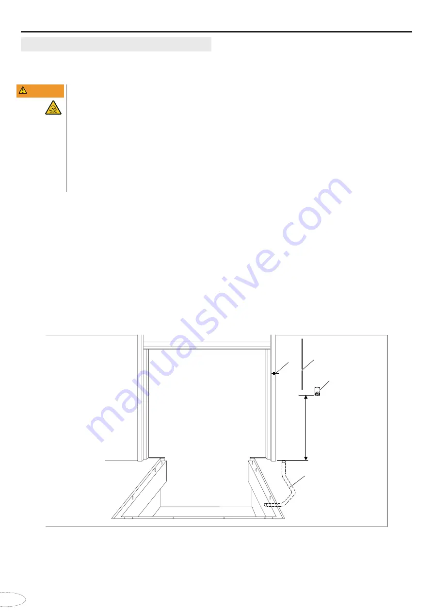
Position and design of the empty conduit
(Ø 70 mm) for laying the cable according to the
installation drawing.
•
The mains connection is available near the
control unit's place of installation.
Additional requirements for installation situations
CZ, DZ1 and DZ2:
•
The pegs are mounted according to the
installation drawing.
1
4
0
0
4
1
3
2
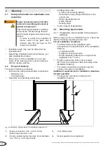
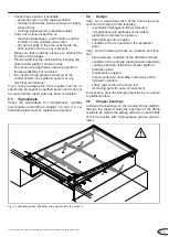
Fig. 6:
Exemplary representation for installation situation CZ
1
Mains connection: 3 N~, 400 V, 50 Hz
Main fuse protection: 10 A
3
16 A CEE socket
2
Empty conduit (cable channel), inner diameter
min. 70 mm, ≤ 45° pipe bends
4
Sensor position door (optional)
Summary of Contents for NovoDock L530
Page 139: ...A3 c 4 x...
Page 141: ...A5 c 4 x 181 250 mm DZ2 100 180 mm DZ1...
Page 150: ......
Page 151: ......
Page 152: ...docking Solution und Service GmbH Springrad 4 30419 Hannover Germany DS0805301 05 2022...

