EN - 41
These assembly, operation and maintenance instructions must be kept for the entire period of use!
•
Check these options, if available:
– automatic return to the resting position
– locking of door/dock leveller (sensor) or safety
wheel chock
– warning signal system (optical/acoustic)
•
Carry out a visual inspection on:
– mechanical damages, rust formation and the
condition of the welded construction
– dirt and oil spills in the area underneath the
dock leveller. Remove any if present.
•
Make sure that no debris, stones etc. obstruct the
function of the hinges.
•
Provide sufficient slip resistance by keeping the
dock leveller platform clean and dry.
•
Do not use any aggressive cleaning agents or
thawing salts! Risk of corrosion:
•
Do not aim a high-pressure water jet at the
control system, the hydraulic system or any
electrical connections!
If you notice damages the dock leveller must be in-
spected by an expert/ a qualified person and must not
be used until the repair work has been completed.
8.3
Signs/labels
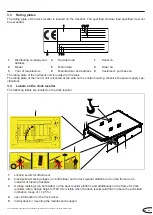
Check the signs/labels for completeness, legibility
and condition according to chapter 3.3 and 3.4. La-
bels/rating plate must be replaced as required.
8.4
Design
Carry out a visual inspection of the entire steel con-
struction with regard to the following:
•
mechanical damages to the weld seams
•
completeness and tightness of the safety
elements and screw connections
•
deformations and corrosion
•
condition of the connection to the installation
point
Carry out the following checks on condition and func-
tion:
•
slip resistance condition of the drivable surfaces
•
condition of the anti-slip coating/sound-absorbing
coating (optional) of the dock leveller platform
•
protective plate
•
maintenance support
•
screw connection and safety cotter pins of the
hydraulic cylinders
•
safety cotter pins at the cross rod
•
all moving parts for ease of movement
If necessary, have the design inspected by an expert/
a qualified person.
8.5
Hinges/ bearings
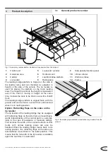
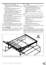
Lubricate the bearings on the loading bridge platform
through the tapered holes,the bearings of the lifting
cylinders as well as the sliding surfaces on both sides
of the lip leveller with multi-purpose grease (see ar-
rows).
Fig. 7:
Lubrication points, illustration may deviate from the product
Summary of Contents for NovoDock L530
Page 139: ...A3 c 4 x...
Page 141: ...A5 c 4 x 181 250 mm DZ2 100 180 mm DZ1...
Page 150: ......
Page 151: ......
Page 152: ...docking Solution und Service GmbH Springrad 4 30419 Hannover Germany DS0805301 05 2022...

