background image

67

70

73

74

68

71

69

72

63

Summary of Contents for NovoPorta Premio E-S-1

Page 1: ...tions T30 1 T30 2 NovoPorta Premio T90 1 T90 2 NovoPorta Premio MZ 1 MZ 2 NovoPorta Premio E S 1 E S 2 NovoPorta Premio 01 2018 Montagehandleiding T30 1 T30 2 NovoPorta Premio T90 1 T90 2 NovoPorta Premio MZ 1 MZ 2 NovoPorta Premio E S 1 E S 2 NovoPorta Premio NL ...

Page 2: ...ungen 111 Schwellenvarianten 112 Sonstige Ausstattungen Mittelfalzdichtung nur zweiflügeligeTüren 50 Hinweise Oberteile 114 Wetterschenkel nur MZ und E S Türen 116 Drücker und Wechselgarnituren 117 Türantriebe 118 Türschließer 120 Sturzfutterwinkel 121 Schließfolgeregler nur zweiflügeligeTüren 122 Mittelfalzverriegelung nur zweiflügeligeTüren 124 Feststellanlagen 125 Kürzen der Eckzarge vor Ort 12...

Page 3: ... am Einbauort geeignet ist die Eigenschaften des Produkts für den Einsatzzweck geeignet sind die erforderliche Öffnungsrichtung ob weitere Bauvorschriften zu erfüllen sind Personenkreis Der Einbau darf nur von montageerfahre nen sachkundigen Personen durchgeführt werden die über ausreichende Fachkennt nis im Umgang mit Feuerschutzabschlüs sen verfügen und Kenntnis der allgemeinen und speziellen Si...

Page 4: ... müssen immer mit Türschließer ausgerüstet sein Türen mit Brandschutzverglasung Türen für den Einbau in Porenbeton Türen für den Einbau in Montagewände nach DIN oder nach AbP Allgemeines bauaufsichtliches Prüfzeugnis Aus nahme Flügelmaße 1000 x1000 mm Rauchschutztüren Türen mit Flügelgewicht 80 kg Zweiflügelige Feuerschutzabschlüsse Außerhalb der Bundesrepublik Deutsch land können andere Vorschrif...

Page 5: ...tigen Pulver grundierung versehen Bei Überlackierungen bitte beachten Die Oberflächen müssen angeschliffen und gereinigt werden Anschließend ist eine einschichtige Überlackierung mit 2KPUR Lösungs mittellack erforderlich Alternativ kann mit lösungsmittelhalti gem 2K Epoxidgrund zwischenlackiert und mit handelsüblichen zinkverträg lichen Kunstharzlacken fertiglackiert werden Eine fachgerechte Endla...

Page 6: ...165 Festigkeits klasse 4 allg bauaufs zugelassen Festigkeitskl 4 liegend oder stehend an geordnet T30 1 Wandklappe von 500 x 700 bis 1000 x 1750 von 416 x 616 bis 916 x 1666 115 100 100 130 150 150 T30 1 Tür von 625 x 1750 bis 1375 x 2500 von 541 x 1708 bis 1291 x 2458 250 kg 115 100 100 130 150 150 T30 2 von1375 x 1750 bis 2500 x 2500 von1291 x 1708 bis 2416 x 2458 250 kg 115 100 100 130 150 150 ...

Page 7: ...ntage Anschweißmontage Falz Schraubmontage Eck Ergän zungszarge Spiegel 30 mm Schraubmontage Dübelmontage Anschweißmontage Blockzarge Typ1 Schraubmontage Blockzarge Typ2 Schraubmontage Blockzarge Typ3 Schraubmontage Blockzarge Typ5 Anschweißmontage Blockzarge Typ6 Anschweißmontage T90 bei verschiedenen Wandarten und mit verschiedenen Zargen Eckzarge Schraubmontage Dübelmontage Anschweißmontage Fal...

Page 8: ...m Hersteller abgestimmten Änderung des Produktes verliert diese Er klärung ihre Gültigkeit Werden die genannten Produkte nicht als Außentür verwendet haben die Regelungen der Bauproduktenverordnung dafür keine Gültigkeit Hinweis Eine Leistungserklärung ist nur für CE gekennzeichnete Türen ver fügbar Die zu Ihrem Produkt passende Leistungserklärung kann über die Num mer auf der CE Kennzeichnung sie...

Page 9: ...m ein flgl T30 1 FSA und T90 1 FSA 8 7 5 T30 1 RS FSA und T90 1 RS FSA 8 2 5 MZ 1 rauchdicht 8 2 5 E S 1 rauchdicht 8 2 5 zwei flgl T30 2 FSA und T90 2 FSA 8 7 5 T30 2 RS FSA und T90 2 RS FSA 8 2 5 MZ 2 rauchdicht 8 2 5 E S 2 rauchdicht 8 2 5 Ankerlagen Bei RS Ausführung immer untere Dichtung verwenden Bei Zargen Wandanschlüs sen mit Mörtelhinterfüllung dauerelastische Versiegelung nicht erforderl...

Page 10: ...Zulässige Maßabweichungen der Wand öffnungen nach DIN 18100 Hat die Rohbauöffnung Mauerwerk Beton Porenbeton nicht ausreichend Platz für die Schutzkästen der Zarge müssen diese Schutzkäs ten in der Wandöffnung ausgestemmt werden Um die Funktion der Tür zu gewährleisten dürfen die Schutzkästen nicht entfernt werden Bei Überschreitung der Toleranzmaße ist eine einwandfreie Funk tion und Standfestigk...

Page 11: ...zarge erforderlich Die Türbänder müssen mit zusätzlichen Band sicherungen durch Gewindestift ver sehen sein Diese Sicherungen müssen vollständig eingeschraubt sein Die Tür muss gemäß ihrer Klassifizierung mit einem Schutzbeschlag nach DIN 18257 ausgestattet sein RC1N ES1 RC2 WK2 ES1 RC3 WK3 ES2 Der Profilzylinder muss der DIN 18252 Klasse P2 BZ entsprechen und außen Angriffseite mit dem Schutzbesc...

Page 12: ...echt und waagerecht nach Meterriss ausrichten und fixieren Schritt 5 Löcher für Dübel bohren zu ge lassene Dübel einsetzen und Zarge mit den beiliegenden Schrauben befestigen Bei Verwendung ohne Bodeneinstand kann die Zarge gekürzt werden Schritt 6 Zarge hinterfüllen bei der zweiteiligen Umfassungszarge 2140B muss die Gegenschale nicht hinterfüllt werden Hinterfüllungen ab Seite 104 Schritt 7 Dick...

Page 13: ...rüfen des Glases durch Sicht kontrolle auf Einläufe und Sprünge Wartungs und Sicherheitsprüfung Die Wartungsintervalle sind nach der Nutzungshäufigkeit jedoch mindestens einmal pro Jahr durchzuführen Die nachfolgenden Wartungsanweisungen stellen den Mindestumfang der durchzuführenden Wartungsarbeiten dar Bauteil Ausführung Bänder 3 D Objektbänder 3 D Objektbänder sind wartungsfrei Keinesfalls schm...

Page 14: ...ttel zu befra gen 4 Instandhaltung und Wartung Hinweis Als Ersatz von beschädigten oder funktionslos gewordenen Teilen Beschlag Zubehör Dichtungen Glas usw dürfen nur die Original Ersatzteile verwendet werden Die ordnungsgemäße und regelmäßige Instandhaltung Wartung Pflege Ins pektion Instandsetzung und Verbesse rung ist die Pflicht des Betreibers Die ordnungsgemäße Instandhaltung ist nicht Bestan...

Page 15: ...auf Beschädigung und auf Vollständigkeit zu überprüfen und ggf auszubessern oder zu erneuern Sollte ein außergewöhnliches Ereignis z B durch Stoß Hagel etc vorgefallen sein so sind unmittelbar nach dem Ereignis eine Kontrolle und ggf Instandsetzungen durchzuführen um Folgeschäden zu vermeiden Schlösser Falle und Riegel sind auf Gängigkeit zu prüfen Eventuell ist bei zurückgezogener Falle etwas Gra...

Page 16: ...e Maintenance and safety checks 27 Cleaning and care 28 NovoPorta Premio for use outdoors 28 ASSEMBLY DETAILS Frame versions 44 Frame fixation 45 Two piece closed frame 2140B Masonry concrete porous concrete Fixation using screws 46 Masonry concrete Fixation using wall plugs 52 Fixation using rebate screws 54 Porous concrete Weld fixation 56 F60 A F90 A dry partition wall Fixation using screws 58 ...

Page 17: ...pproval documentation that the product is suitable for the conditions at the installation site that the product has the properties required for its intended purpose the correct opening direction whether there are any further construc tion conditions to be satisfied Suitable persons Installation should be carried out only by experienced and appropriately skilled persons who have sufficient speciali...

Page 18: ...e German Model Building Regulation The operator is responsible for the door remaining in good working order The following fire protections barriers must always be equipped with door closing mechanisms Doors with fire protection glazing Doors for installation in porous concrete Doors for installation in walls conforming to DIN or AbP German general building inspection test certificate Exception Doo...

Page 19: ...r coat please note The surface must be sanded and cleaned It will be necessary to apply one final coat using 2KPUR solvent based paint afterwards Alternatively one may apply a layer of 2K epoxi primer containing solvents and then apply a final coat of conventional zinc compatible synthetic lacquer paint The correct final painting must be carried out within three months of assembly Otherwise we can...

Page 20: ... compressive strength 4 Approved for general con struction compressive strength 4 laid horizontally or vertically T30 1 Wall vent from 500 x 700 to 1000 x 1750 from 416 x 616 to 916 x 1666 115 100 100 130 150 150 T30 1 Door from 625 x 1750 to 1375 x 2500 from 541 x 1708 to 1291 x 2458 250 kg 115 100 100 130 150 150 T30 2 from1375 x 1750 to 2500 x 2500 from1291 x 1708 to 2416 x 2458 250 kg 115 100 ...

Page 21: ...bate screws Corner supple mentary frame frame face 30 mm Fixation using screws Fixation using wall plugs Weld fixation Block frame Type1 Fixation using screws Block frame Type2 Fixation using screws Block frame Type3 Fixation using screws Block frame Type5 Weld fixation Block frame Type6 Weld fixation T90 for a variety of wall types and with different frames Corner frame Fixation using screws Fixa...

Page 22: ...d In case of any change to the product not agreed with the manufacturer this declaration shall lose any force If the said products are not used as an ex terior door this circumstance will remove the applicability of the terms of the regula tions on construction products Note Declarations of performance will be available only for doors with the CE mark The declaration of performance matching your p...

Page 23: ...esistant plasterboard wall masonry concrete porous concrete fire resistant plasterboard wall Floor ventilation slit Door type NovoPorta Premio in mm Single leaf T30 1 FSA and T90 1 FSA 8 7 5 T30 1 RS FSA and T90 1 RS FSA 8 2 5 MZ 1 smoke proof 8 2 5 E S 1 smoke proof 8 2 5 Double leaf T30 2 FSA and T90 2 FSA 8 7 5 T30 2 RS FSA and T90 2 RS FSA 8 2 5 MZ 2 smoke proof 8 2 5 E S 2 smoke proof 8 2 5 A...

Page 24: ...rdance with DIN 18100 If the gross construction openings masonry concrete porous concrete do not offer sufficient space for the protective boxes of the frame box the wall openings must be chiselled out for the protective boxes In order to ensure the functioning of the door the protective boxes must not be removed Where the dimensional tolerances are exceeded the correct functioning and stability o...

Page 25: ...s required Door seals must be provided with additional hinge fixation using a grub screw These fixations must be screwed in fully Depending on its classification the door must be equipped with security plates conforming to DIN 18257 RC1N ES1 RC2 WK2 ES1 RC3 WK3 ES2 The profile cylinder must conform to DIN 18252 Class P2 BZ and on the exterior on the handle side must lie flush with the se curity pl...

Page 26: ...t the frame vertically and horizontally to the guide marking and fix it in place Step 5 Drill the holes for the wall plugs insert approved wall plugs and fasten the frame using the screws provided Where a frame is being used with out a floor recess it can be trimmed at the bottom Step 6 Back fill the frame with two piece closed frame 2140B the counterframe does not need to be backfilled Backfills ...

Page 27: ...nce intervals will depend on intensity of use but should take place a minimum of once a year The maintenance instructions set out below represent the minimum scope of the maintenance tasks to be carried out Component Version Hinges 3D hinges 3D hinges are maintenance free Under no circumstances lubricate All other hinges Undo clean and lubricate hinge bolts Pressure ball bearings Where you detect ...

Page 28: ... rol are unsuitable and may cause ir reparable damage In case of doubt please ask the manufacturer about the suitability of the cleaning agent 4 Maintenance and care Note Only original replacement parts should be used as a substitute for dam aged or non functioning parts fittings accessories seals glass etc Proper and regular upkeep mainte nance care inspection repair and improvement of the produc...

Page 29: ...ked annually for damage and completeness and repaired or re newed as necessary If some unusual incident e g an impact or heavy hail etc should occur then immediately after the incident a check should be made and remedial measures taken in order to prevent downstream damage Locks The free movement of latches and bolts should be checked In cases where latches are jammed graphite oil can be sprayed i...

Page 30: ...ing rookbeveiliging inbraakbeveiliging 39 Zo monteert u uw deur In 13 stappen naar een gemonteerde deur 40 Onderhoud reiniging en verzorging Onderhouds en veiligheidscontrole 41 Reiniging en service 42 Buitendeuren 43 MONTAGEDETAILS Kozijnsoorten 44 Kozijnbevestiging 45 Tweedelig kozijn 2140B Metselwerk beton gasbeton Schroefmontage 46 Metselwerk beton Plugmontage 52 Verdekte montage 54 Gasbeton L...

Page 31: ...chappen van het product geschikt zijn voor het gebruiksdoel de juiste openingsrichting of er overige bouwvoorschriften gelden Bevoegde personen De inbouw mag uitsluitend worden uit gevoerd door deskundige personen die ervaring met montage hebben en die vol doende vakkennis hebben wat betreft de omgang met brandwerende afsluitingen en kennis van de algemene en specifieke voorschriften voor veilighe...

Page 32: ...en moeten altijd met een deurdranger voor zien zijn Deuren met brandwerend glas Deuren voor de inbouw in gasbeton Deuren voor de inbouw in montagemuren conform DIN of conform AbP keurings rapport bouwinspectie uitzondering vleugelafmetingen 1000x1000 mm Rookwerende deuren Deuren met vleugelgewicht 80 kg Tweevleugelige brandwerende afsluitin gen Buiten de Bondsrepubliek Duitsland kun nen andere voo...

Page 33: ...andaard voorzien van een hoogwaardige poedercoating grondlak Let bij overlakken op het volgende De oppervlakken dienen te worden ge schuurd en gereinigd Aansluitend dient u één laag eroverheen te lakken met 2KPUR mediumlakoplos ser Als alternatief kan ook een oplosmiddel houdend 2K Epoxidgrund een tussenlaag worden aangebracht en met een stan daardkunstharslak die bestand is tegen zink de afronden...

Page 34: ...s klasse 4 alg keurings rapport bouw inspectie weer standsklasse 4 liggend of staand voor geschreven T30 1 Wandluik van 500 x 700 tot 1000 x 1750 van 416 x 616 tot 916 x 1666 115 100 100 130 150 150 T30 1 Deur van 625 x 1750 tot 1375 x 2500 van 541 x 1708 tot 1291 x 2458 250 kg 115 100 100 130 150 150 T30 2 van 1375 x 1750 tot 2500 x 2500 van 1291 x 1708 tot 2416 x 2458 250 kg 115 100 100 130 150 ...

Page 35: ... 1 Plugmontage Lasmontage Verdekte montage Hoek tegenkozijn spiegel 30 mm Schroefmontage Plugmontage Lasmontage Blokkozijn type 1 Schroefmontage Blokkozijn type 2 Schroefmontage Blokkozijn type 3 Schroefmontage Blokkozijn type 5 Lasmontage Blokkozijn type 6 Lasmontage T90 bij verschillende muursoorten en met verschillende kozijnen Hoekkozijn Schroefmontage Plugmontage Lasmontage Verdekte montage T...

Page 36: ...roleerd Bij een niet met de fabrikant afgestemde wijziging van het product ver liest deze verklaring haar geldigheid Indien de vermelde producten niet als buitendeur worden gebruikt hebben de bepalingen van de Bouwproductenrichtlijn hiervoor geen geldigheid NB Een prestatieverklaring is alleen beschikbaar voor deuren met CE certifi cering U kunt de bij uw product horende prestatieverklaring opvrag...

Page 37: ... vlgl T30 1 FSA en T90 1 FSA 8 7 5 T30 1 RS FSA en T90 1 RS FSA 8 2 5 MZ 1 rookdicht 8 2 5 E S 1 rookdicht 8 2 5 twee vlgl T30 2 FSA en T90 2 FSA 8 7 5 T30 2 RS FSA en T90 2 RS FSA 8 2 5 MZ 2 rookdicht 8 2 5 E S 2 rookdicht 8 2 5 Bevestigingen Bij RS uitvoering altijd onderste afdichting gebruiken Bij kozijnmuurafsluitingen met mortelvulling is geen blijvende elastische verzegeling nodig anders mo...

Page 38: ... bij de montage van hoekkozijnen is het ver draaien van de lengtedelen van de kozijnen wegens functionerings technische redenen niet toegestaan Metselwerk Breedte bestelmaatbreedte 20 0 mm Hoogte bestelmaathoogte 15 0 mm F60 A F90 A metal stud Breedte bestelmaatbreedte 10 0 mm Hoogte bestelmaathoogte 5 0 mm F60 B F90 B hout stud Breedte bestelmaatbreedte 10 0 mm Hoogte bestelmaathoogte 5 0 mm FOUT...

Page 39: ...edig vast zijn geschroefd De deur dient conform haar classificatie te zijn voorzien van een beschermingsrand conform DIN 18257 RC1N ES1 RC2 WK2 ES1 RC3 WK3 ES2 De profielcilinder dient conform DIN 18252 klasse P2 BZ te zijn en aan de buitenkant aanpakkant goed aan te sluiten op de beschermingsrand De in de profielcilinder geïntegreerde trekbescherming is niet nodig indien de trekbescherming reeds ...

Page 40: ...en verticaal uit op basis van de metermarkering en zet het vast Stap 5 Boor gaten voor pluggen plaats de toegestane pluggen en bevestig het kozijn met de meegeleverde schroeven Bij gebruik zonder vloeruitsparing kan het kozijn worden ingekort Stap 6 Vul het kozijn bij het tweedelige muuromvattende kozijn 2140B heeft de tegenzijde geen vulling nodig Vullingen vanaf pagina 104 Stap 7 Breng de sponni...

Page 41: ... brand opschuimen vervangen 4 Controlerenvanhetglasd m v visuelecon trole op inlopen en sprongen Onderhouds en veiligheidscontrole De onderhoudsintervallen dienen op basis van de mate van gebruik maar minstens eenmaal per jaar te worden uitgevoerd De volgende onderhoudsinstructies geven de minimale omvang van de uit te voeren onderhoudswerkzaamheden weer Bouwdeel Uitvoering Scharnieren 3 D scharni...

Page 42: ... niet beoogd gebruik van het product van buiten deuren valt onder meer Als obstakels in de openingszone van deur worden geplaatst en daar door het beoogde gebruik niet meer mogelijk is Bij buitendeuren met paniek en nooduitgangsfunctie EN 179 EN 1125 is de nooduitgangsfunctie alleen met eruit getrokken sleutel gewaarborgd Als buitendeuren of deurvleugels ondoelmatig of ongecontroleerd bijv door wi...

Page 43: ...delen chemisch verenigbaar zijn Oppervlakken Er dient elk jaar te worden gecontroleerd of oppervlakken beschadigd of nog compleet zijn en indien nodig dienen zij te worden verbeterd of vervangen Indien er iets buitengewoons is voorgevallen bijv door stoten hagel enz dient er direct na het voorval een controle en evt herstel uit te worden gevoerd om gevolgschade te voorkomen Sloten Dagschoot en nac...

Page 44: ...the width of the mounting plate Corner frame Image 1 below Corner frame with supplementary frame Image 2 below Corner frame with counterframe Image 3 below Block frame Type 1 wall corner Installation in doorjamb Image 4 below Block frame Type 2 with edging Installation in doorjamb Image 5 below Block frame Type 3 Installation in front of wall Image 6 below Closed frame Image 7 below Closed frame 2...

Page 45: ...nnection bracket 4 Corner frame 5 Counterframe Screw on the nuts for the connection and corner bracket max 10 Nm Mount the sill bracket to the longitudinal parts of the frame so that the mitre fits snugly into the corners Image 10 below 1 Sill bracket The frame may be welded onto the cor ners where required After screwing the frame onto the weather board where there is one see page 116 Zargenversc...

Page 46: ...t the adapter and counteradapter offset from one another Two screws should be used per adapter Images 16 17 on right hand side Check the frame for correct horizontal and vertical positioning and tighten up the screws Backfill the frame in accordance with approval documentation see page 104ff Move special 2140B counterframe slightly tilted from above into the lowest counter adapter and then positio...

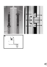
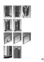
Page 47: ...13 14 15 18 19 20 21 22 1 2 12 16 17 11 47 ...

Page 48: ...t the ventilation slit between the door leaf and the frame in mirror image The door leaf is fixed to the frame using the screws 2 c If required a securing pin also suita ble for retrofitting can be used to pre vent the hinge bolt coming loose With the door open twist steel pin into the threaded borehole for the construction hinge 3 and spring hinge 4 d If the spring pin for spring hinge locking ca...

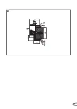
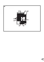
Page 49: ...2 1 25 23 24 1 1 2 3 4 5 1 49 ...

Page 50: ...äge und Zubehör Seals fittings and accessories Hinweis Die Schwelle darf nach der Montage entfernt werden Bei Montage ohne Bodeneinstand der Zarge siehe Seite 126 muss an beiden Zargenlängs teilen ein zusätzlicher Anker in Höhe 60 20 mm ab OFF angebracht werden Nicht bei MZ Türen Türschließer montieren siehe Seite 120 Note The sill must be removed after as sembly Where installing the frame with ou...

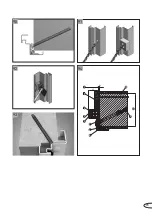
Page 51: ...2 5 mm 30 31 1 29 28 27 26 51 ...

Page 52: ...he wall plug brackets on the 2140B counterframe Align the 2140B counterframe to the corner frame and push it into the corner frame until it clicks into place Images 35 36 on right hand side The groove in the corner frame is factory pre perforated Fix the supplementary frame to the corner frame with the self drilling screws provided For standard doors without factory pre prepared holes in the seal ...

Page 53: ...1 2 3 1 2 3 1 1 2 2 3 3 33 34 35 36 37 38 32 53 ...

Page 54: ...ce with approval documentation see page 104ff Align the 2140B counterframe to the corner frame and push it into the corner frame until it clicks into place Images 42 43 on right hand side The groove in the corner frame is factory pre perforated Screw the corner and 2140B counterframe together with the 3 9x32 self drilling screws through these holes For standard doors without factory pre prepared h...

Page 55: ...41 42 43 44 45 1 1 8 9 4 2 3 7 6 10 5 11 45 5 5 lt 39 40 55 ...

Page 56: ... must be removed form weld joints and they must be cold galvanised and primed Image 46 on right hand side 1 Coordinating size 2 Nominal dimensions 3 Porous concrete 4 Frame backfilling with mineral mortar 5 Primed weld seam 6 Cut back fixation bracket before installation 7 Wall plug conforming to general construction approval 8 Wall thickness see table on page 20 Zarge einbauen Umfassungszarge 214...

Page 57: ...84 5 45 34 50 48 3 2 1 4 5 6 5 6 7 8 46 57 ...

Page 58: ...drilling screw is required for each frame fixation point Images 50 51 on right hand side Check the frame for correct horizontal and vertical positioning and tighten up the self drilling screws Backfill the frame in accordance with approval documentation see page 104ff Move special 2140B counterframe slightly tilted from above into the lowest counter adapter and then position inside the open ing Im...

Page 59: ...47 50 52 55 48 51 53 56 49 54 59 ...

Page 60: ...oosely onto the U A profile using the 6 3x32 self drilling screws provided No counteradapter is required for the two upper fixation points simply fasten the screw directly onto the adapter ONLY ONE self drilling screw is required for each frame fixation point Images 60 61 on right hand side Check the frame for correct horizontal and vertical positioning and tighten up the self drilling screws Back...

Page 61: ...60 62 65 58 61 63 66 59 64 57 61 ...

Page 62: ...ed Image 69 on right hand side Mount the counteradapter over or under the adapter of the corner frame For secure fastening mount the counteradapter with 2 5 mm thick lining material under it Move the corner frame into the opening until it almost clicks into place align it horizontally and vertically and against the guide marking Backfill the frame in accordance with approval documentation see page...

Page 63: ...67 70 73 74 68 71 69 72 63 ...

Page 64: ...e 14 brackets for double leaf doors use 17 brackets onto the corner frame at the corresponding fixation points and onto the square piping Align the 2140B counterframe to the corner frame and push it into the corner frame until it clicks into place The groove in the corner frame is factory pre perforated Screw the corner and 2140B counterframe together with the 3 9x32 self drilling screws through t...

Page 65: ...45 39 48 1 6 8 9 5 10 2 3 4 75 65 ...

Page 66: ... correct horizontal and vertical positioning and tighten up the screws Align the counteradapter to the height of the adapter and fasten it onto the wall No counteradapter is required for the two up per fixation points Image 78 on right hand side Backfill the frame in accordance with approval documentation see page 104ff Move special 2140B counterframe slightly tilted from above into the lowest cou...

Page 67: ...76 77 79 80 81 82 83 78 67 ...

Page 68: ... 2 mm tolerance in the masonry push the clamping plates 3 mm into the space between fixation brackets and the masonry Image 86 on right hand side 1 Clamping plate Fasten the frame loosely and fix it between the fixation brackets and the bolt using clamping plates Tighten up the bolt between the frame and the wall using an open jawed spanner Please make sure that the frame profiles do not rotate wh...

Page 69: ...1 1 5 5 1 1 1 4 3 2 7 6 8 5 9 10 42 53 1 3 2 1 84 85 86 87 69 ...

Page 70: ...pace remove the frame mark and then drill the wall plug holes and insert wall plugs Fasten the frame loosely with the screws provided Please make sure that the frame profiles do not rotate while they are being fastened down Check the frame for correct horizontal and vertical positioning and tighten up the screws Backfill the frame in accordance with approval documentation see page 104ff Visible fi...

Page 71: ...1 2 3 1 2 3 1 1 2 2 3 3 1 2 3 4 6 9 6 8 5 11 7 10 42 5 5 88 89 71 ...

Page 72: ...angle Image 91 on right hand side Insert wall plugs at least 160 mm in masonry or 100 mm in concrete Fasten frame to the pre set points on the wall using the screws provided using only one screw per fixation point using spacing plates where necessary Cover frame holes with borehole plugs Images 92 93 on right hand side Backfill the frame in accordance with approval documentation see page 104ff Ima...

Page 73: ...1 9 4 2 3 5 11 10 7 6 8 42 5 5 93 94 90 91 92 73 ...

Page 74: ...ing to general construction approval 6 Fixation bracket 7 Weld separation piece 8 Inset anchor hooks Fl 40x4 9 Masonry concrete 10 Wall thickness see table on page 20 Push corner frame into the opening until it almost clicks into place and line up with the guide marking Weld the corner frame onto the fixation brackets or anchor hooks Backfill the frame in accordance with approval documentation see...

Page 75: ...1 2 4 8 3 9 10 7 42 5 5 1 2 4 6 5 7 3 9 10 42 5 5 100 45 1 2 4 6 5 7 3 9 10 42 5 5 100 45 95 96 97 75 ...

Page 76: ...8 Please note Where installing onto porous concrete the corner frame should always be welded on to the fixation brackets Paint must be removed form weld joints and they must be cold galvanised and primed Image 98 on right hand side 1 Coordinating size 2 Corner frame 3 Frame sealing 4 Frame backfilling 5 Wall plug conforming to general construction approval 6 Fixation bracket 7 Weld separation piec...

Page 77: ...1 4 7 3 2 5 8 9 6 42 5 5 100 98 77 ...

Page 78: ...nd side 1 Coordinating size 2 Corner frame 3 Frame sealing 4 Frame backfilling 5 Wall plug conforming to general construction approval 6 Screwed either welded or riveted 7 Welding spacer facing piece on three sides 8 Counterframe 9 Two screws required on wall thicknesses _ 240 mm 10 Masonry concrete 11 Wall thickness see table on page 20 Frame connection in the jamb Image 100 on right hand side 1 ...

Page 79: ...1 9 8 2 7 4 3 6 10 11 5 42 5 5 45 1 7 4 8 2 3 6 5 10 11 9 42 39 max 69 99 100 79 ...

Page 80: ...te corner and counterframe should always be welded onto the fixation brackets Paint must be removed form weld joints and they must be cold galvanised and primed Image 101 on right hand side 1 Coordinating size 2 Corner frame 3 Frame sealing 4 Frame backfilling 5 Wall plug conforming to general construction approval 6 Self drilling screw 3 9x32 DIN 7504 welded if required 7 Fixation bracket 8 Weld ...

Page 81: ...1 9 7 6 3 10 8 2 4 5 11 12 42 5 5 1 2 1 2 101 81 ...

Page 82: ... the installation aid bracket if you have used one Backfill the frame in accordance with approval documentation see page 104ff The groove in the corner frame is factory pre perforated Fasten the counterframe onto the corner frame using the 3 9x32 self drilling screws provided When screwing in make sure that the two frames are mounted snugly against each other The counterframe is factory pre holed ...

Page 83: ...1 2 4 3 9 8 5 6 7 10 48 82 100 50 102 103 1 83 ...

Page 84: ...lastered over Stick down the optional covering strip in the supplementary frame if the supplementary frame has not been backfilled where the corner frame is backfilled with fire protec tion foam this strip is absolutely necessary in order to protect the foam from UV rays Image 104 on right hand side 1 Coordinating size 2 Corner frame 3 Frame sealing 4 Frame backfilling 5 Wall plug conforming to ge...

Page 85: ...1 10 9 7 4 3 2 6 8 5 11 12 42 5 5 104 85 ...

Page 86: ...gh the factory pre holed adapter and insert the wall plugs e Fasten the frame loosely using the screws provided 4 Please make sure that the frame profiles do not rotate while they are being fastened down f Backfill the frame in accordance with approval documentation see page 104ff g Check the frame again for correct horizontal and vertical positioning and tighten up the screws 4 h Close up holes w...

Page 87: ...1 2 3 4 5 1 2 3 4 105 1 8 4 9 5 6 3 7 2 10 40 45 1 8 11 9 6 6 2 3 7 4 5 10 40 106 107 87 ...

Page 88: ...des with the screws provided Please make sure that the frame profiles do not rotate while they are being fastened down Backfill the frame in accordance with approval documentation see page 104ff Check the frame for correct horizontal and vertical positioning and tighten up the screws Where installing using wall plugs the counteradapter and fixation bracket must be entirely plastered over Image 108...

Page 89: ...1 7 6 9 5 6 2 4 8 42 x5 30 31 50 40 108 89 ...

Page 90: ...rame piece 15 Masonry concrete 16 Wall thickness see table on page 20 17 Two screws required on wall thicknesses _ 240 mm Fitting frame Closed frame Weld fixation into masonry concrete Closed frame Image 109 on right hand side Closed frame with shadow groove Image 110 on right hand side Closed frame with counterframe Installation in walls 450 mm Image 111 on right hand side Closed frame with count...

Page 91: ...1 5 15 4 3 2 6 16 40 5 5 45 6 5 6 2 3 8 4 7 1 15 17 16 40 5 5 45 1 12 15 5 4 3 6 2 16 7 11 45 40 5 5 7 9 1 5 2 7 6 3 4 10 16 14 13 40 5 5 175 100 3 x20 200 30 109 111 110 112 91 ...

Page 92: ... Fasten the frame loosely with the screws provided Please make sure that the frame profiles do not rotate while they are being fastened down Check the frame for correct horizontal and vertical positioning and tighten up the screws Backfill the frame in accordance with approval documentation see page 104ff Close up holes with plugs Images 116 119 on right hand side 1 Coordinating size 2 Block frame...

Page 93: ...4 6 11 2 5 8 3 7 9 12 70 1 4 8 3 2 10 6 7 11 12 5 42 39 50 9 70 1 2 3 1 2 3 1 2 3 4 7 2 3 8 9 6 5 11 1 13 42 39 9 2 1 12 5x45 36 11 1 6 7 11 4 3 8 2 10 5 13 42 39 50 9 116 118 117 119 113 114 115 93 ...

Page 94: ...es for wall plugs remove the frame from the opening drill and insert wall plugs Remove the mineral wool inserts in the area of the boreholes in the frame Fasten the frame loosely with the screws provided Please make sure that the frame profiles do not rotate while they are being fastened down Check the frame for correct horizontal and vertical positioning and tighten up the screws Close up holes w...

Page 95: ...97 61 1 3 2 6 5 4 7 120 95 ...

Page 96: ...e remaining fixation brackets and the frame together Paint must be removed form weld joints and they must be cold galvanised and primed Block frame Type 5 6 Images 121 122 on right hand side 1 Coordinating size 2 Block frame 3 Frame sealing 4 Frame backfilling 5 Wall plug conforming to general construction approval 6 Fixation bracket 7 Weld separation piece 8 Welding spacer facing piece on three s...

Page 97: ...1 4 3 2 6 9 10 5 7 42 39 max 69 1 4 3 2 9 10 5 7 6 42 39 max 69 121 122 97 ...

Page 98: ...neral wool strips min 150 kg m 8 Plugs 9 Fixation bracket 10 Edging 11 Porous concrete 12 Wall thickness see table on page 20 13 Continuous wall Block frame Type 1 Installation in doorjamb Image 123 on right hand side Installation in continuous wall Image 124 on right hand side Block frame Type 2 with edging Installation in doorjamb Image 125 on right hand side Installation in continuous wall Imag...

Page 99: ...7 9 2 4 8 3 6 11 5 12 1 4 2 8 3 6 7 11 5 12 10 42 39 50 9 70 1 11 6 5 13 4 3 8 2 7 42 39 9 70 1 4 2 3 8 10 5 6 11 7 13 42 39 50 9 123 125 124 126 99 ...

Page 100: ... 45 Assemble block frame as described on page 96 Block frame Type 5 6 Image 127 on right hand side 1 Coordinating size 2 Block frame 3 Frame sealing 4 Frame backfilling 5 Wall plug conforming to general construction approval 6 Fixation bracket 7 Weld separation piece 8 Porous concrete 9 Wall thickness see table on page 20 Continued on page 48 Schroef het kozijn samen indien het niet is gelast zie ...

Page 101: ...1 8 6 5 9 4 2 3 7 42 39 max 69 127 101 ...

Page 102: ...ile using the 6 3x60 self drilling screws provided Please make sure that the frame profiles do not rotate while they are being fastened down Check the frame for correct horizontal and vertical positioning and tighten up the self drilling screws Backfill the frame in accordance with approval documentation see page 104ff Close up holes with plugs Images 128 129 on right hand side 1 Coordinating size...

Page 103: ...1 11 5 6 7 13 2 9 12 14 4 3 8 42 39 2 5 70 125 1 11 5 14 8 3 2 4 7 10 13 12 42 39 50 2 5 70 125 128 129 103 ...

Page 104: ...the frame Spray the space between frame and wall with a water spray bottle This will increase the expansion effect of the foam Image 130 on right hand side Then attach the foam can onto the gun and apply the foam in two phases First the deeper spaces then the ones further for ward Image 131 on right hand side After allowing the foam to dry at least 30 minutes remove the excess foam with a sharp kn...

Page 105: ...130 131 132 105 ...

Page 106: ...nto position Insert stepped profile In the case of the two piece 2140B closed frame after backfilling the corner frame install the special 2140B counterframe According to the product approval the latter can be left empty For the block frame make sure that the entire frame is backfilled with Novoferm mineral wool as product approval will otherwise be invalid Where you have any difficulty holding th...

Page 107: ...133 135 134 107 ...

Page 108: ...jamb with circa 48 mm wide strip of loose fibre mineral fibre with minimum density 40 kg m with melting point 1 000 C construction material class A1 or Euroclass A1 In the case of the two piece 2140B closed frame after backfilling the corner frame install the special 2140B counterframe According to the product approval the latter can be left empty Displayed Two piece closed frame 2140B corner fram...

Page 109: ...nto the rear frame piece before mounting the frame Be careful to leave hinge straps and protective boxes open Then install the frame as described In the case of the two piece 2140B closed frame after backfilling the corner frame install the special 2140B counterframe According to the product approval the latter can be left empty Displayed Two piece closed frame 2140B corner frame and special 2140B...

Page 110: ...ove the spacer between the door fleas the frame has been removed Bei der zweiteiligen Umfassungszarge 2140B nach dem Hinterfüllen der Eckzarge abschließend die spezielle 2140B Gegen zarge montieren Diese kann laut Zulas sung leer bleiben Mörtelhinterfüllung von oben Bild 138 unten In the case of the two piece 2140B closed frame after backfilling the corner frame install the special 2140B counterfr...

Page 111: ...htet wird Bild 139 unten 1 Oberkante Fertigfußboden The seal will be as good as the floor under it An optimal seal is achieved for flat and even and for uneven floors Avoid excessive pressure on floor Exces sive pressure will lead to increased wear on the seal profile on the door s mechanical parts and on fixation points Note on installation of floor seals for smoke protection doors For smoke prot...

Page 112: ... 5 E S 2 rauchdicht 8 2 5 Der Schwellenwinkel bzw die Montage hilfe kann nach der Montage entfernt werden Ein Maßblatt für abweichende Schwellen ausführung finden Sie im Internet unter www novoferm com Floor ventilation slit for single leaf doors Door type NovoPorta Premio in mm T30 1 FSA 8 7 5 T30 1 RS FSA 8 2 5 T90 1 FSA 8 7 5 T90 1 RS FSA 8 2 5 MZ 1 smoke proof 8 2 5 E S 1 smoke proof 8 2 5 Flo...

Page 113: ...20 8 7 5 1 2 6 4 3 20 8 2 5 1 6 4 3 20 20 8 7 5 1 20 8 2 1 3 5 2 1 1 20 8 7 5 1 25 20 8 2 5 1 20 8 2 5 1 140 141 142 146 144 143 147 148 145 113 ...

Page 114: ...screw clamps Image 150 on right hand side With the headless screws in the transom profile push the upper piece up so that the fixation bolts insert into the frame cross piece securely Image 151 on right hand side Adjust the position of the top piece horizon tally where necessary Seal up openings in transom profile with plugs Image 152 on right hand side Images 149 152 on right hand side 1 Transom ...

Page 115: ...4 1 2 3 4 1 2 3 9 7 2 3 8 4 1 149 150 151 152 6 1 5 115 ...

Page 116: ...ge side Den Wetterschenkel Standard Leicht metall auf das Zargenquerteil aufstecken Bild 153 unten 1 Wetterschenkel 2 Zargenquerteil 3 Türblatt Apply the weather guard onto the cross frame component Image 153 below 1 Weather guard 2 Cross frame component 3 Door leaf Regendorpel Montage alleen bij deuren MZ en E S Let op De regendorpel dient vóór montage van het kozijn te worden aangebracht Bij deu...

Page 117: ...chtung Die Schrauben nicht zu fest an ziehen die Tür kann beschädigt werden Attention Do not screw in too tight as this may damage the door Dargestellt Montage einer Drücker garnitur Drücker Drücker Bild 154 unten Displayed Installation of a handle fitting double handle Image 154 below Kruk en wissel garnituren Monteren conform de montagehandleiding van de fabrikant Schuif grondplaat A door de boo...

Page 118: ...la tion instructions of the drive s manufactur er Images 155 160 on right hand side 1 Door drive 2 Frame 3 Wall 4 Door leaf 5 Base plate 6 Sunken screw 7 Screws 8 Wall plug Type installed on hinge side pulling Image 155 on right hand side Type installed on the opposite hinge side pushing Fastening onto wall and onto frame Image 156 on right hand side Fastening onto counterframe Image 157 on right ...

Page 119: ...53 40 1 Alt 1 3 2 4 1 3 4 2 1 3 2 4 1 3 2 4 100 1 3 4 2 6 7 2 8 1 5 3 4 159 158 160 155 156 157 119 ...

Page 120: ...e door closes no matter how far it is open Achtung Es dürfen nur Türschließer nach DIN 18263 Teil 1 oder DIN EN 1154 verwendet werden Das Federband muss leicht vorgespannt werden Attention Only door closers conforming to DIN 18263 Part 1 or DIN EN 1154 may be used The spring hinge must be pre tensioned slightly Bei Feuerschutz und oder Rauchschutz abschlüssen müssen mindestens Schließer der Größe ...

Page 121: ...teplättchen mit Schraube 4 8x16 befestigen dargestellt ohne Gleitschiene Bild 166 unten Measure the clearance between frame jambs Determine the bracket lengths and cut off Images 163 166 below 1 Frame 2 Door leaf 3 Clear passage width 4 Bracket length 5 Bracket length for active leaf 6 Bracket length for inactive leaf 7 Cut edge 8 Lintel casing bracket 9 Fastening plate 10 Door closer 11 Smoke ala...

Page 122: ...y arm 5 Stop bracket Fix the mounting plate onto the frame and screw the stay arm onto it Adjust and make other changes in accord ance with the installation instructions of the manufacturer Achtung Bei integrierter Schließfolge regelung siehe Montageanleitung des Herstellers Attention Where there is a door sequence selector see the installation instructions of the manufacturer Sluitvolgorderegelaa...

Page 123: ...1 2 3 4 5 5 167 123 ...

Page 124: ...x30 flat head screw into the threaded hole Image 169 below Assembly on the fixed leaf Install the 80x7x2 foam pad in the recess Image 170 below Then fasten the mushroom cam keep by screwing the M6x16 cheese head screws into the threaded holes Image 171 below Install the 30x7x2 foam pads in front of the mushroom cam keep Image 172 below The mushroom cam and the mushroom cam keep can be aligned by m...

Page 125: ...cturer of the retainer device by staff authorised by the manufacturer or by the specialised staff of test centre authorised to undertake such tests The door retainer must be maintained in working order by the operator at all times and must be checked for proper functioning at least once a year In addition the operator has a duty to conduct a test for proper and fault free interaction of all device...

Page 126: ...rame is too long for its purpose or is being used without a floor recess it can be cut back directly on site In such cases the lower anchor must be used as shown in the illustration on page 23 Cuttable frame with floor recess Image 175 below 1 Additional anchor for use without floor recess 2 Frame cuttable for use without floor recess Inkorten van het hoekkozijn op de bouwplaats Hoekkozijnen zijn ...

Page 127: ...their seal groove If these corner frames are due to be equipped with special 2140B counter frame later then these bore holes should be made before fitting the counterframe Installation situation of frame for single leaf door Image 176 below 1 Standard rebate width 2 Standard rebate height Installation situation of frame for double leaf door Image 177 below 1 Standard rebate width 2 Standard rebate...

Page 128: ...pending on door type in the doors approval documen tation Zulässige Änderungen an bereits hergestellten Feuerschutz abschlüssen Permissible alterations on already installed fire protection barriers U vindt uitgebreide informatie over toege stane wijzigingen aan uw deur af hankelijk van het betreffende deurtype in de attest documentatie Toegestane wijzigingen aan reeds gemonteerde brandwerende afsl...

Page 129: ...129 ...

Page 130: ...130 ...

Page 131: ...131 ...

Page 132: ...strieweg 4 6045 JG Roermond Tel 31 475 346100 E mail industrie novoferm nl www novoferm nl Novoferm Vertriebs GmbH Kunden Service Center Industrie Industriestraße 12 74336 Brackenheim Tel 49 7135 89 0 Fax 49 7135 89 249 E mail vertrieb brackenheim novoferm de www novoferm de www novoferm com Kunden Service Center Handel Schüttensteiner Straße 26 46419 Isselburg Werth Tel 49 2850 910 700 Fax 49 285...

Reviews: