LogBox-AA Data Logger
NOVUS AUTOMATION
2/6
NXPERIENCE SOFTWARE
You must use
NXperience
software to configure and download data
from LogBox-AA. To install the software, simply run the file
NXperience_Setup.exe
, available on our website.
RUNNING NXPERIENCE
When you start
NXperience
, the home screen will appear:
Figure 3 –
NXperience
home screen
Next, at the bottom of the screen, you must click on the button to
indicate the serial port to be used by the
IR-LINK3 Optical Interface
,
which must be connected to the computer USB:
Figure 4 –
Select a device
In the example above you should select the option "USB Serial Port
(COM3)" and click
Ok
. After that, simply click on the
Configure
button and then on
Read Device
to perform the connection process.
Note:
This manual provides basic information on how to configure
the device. For more specific information about other features,
please refer to the
NXperience
manual, available on our website.
IR-LINK3 OPTICAL INTERFACE
To configure, monitor, or download data from the logger through the
NXperience
software, you must use an
IR-LINK3 Communication
Interface
(purchased separately).
IR-LINK3
acts as an intermediary between the device and the
computer being used and allows you to transmit and receive data
from the logger via infrared signals.
The driver will be installed during the
NXperience
installation
process. Once this is done,
IR-LINK3
will be recognized whenever it
is connected to the computer.
CONFIGURING THE LOGGER
To configure the logger,
IR-LINK3 Communication Interface
must
be connected to the computer being used.
IR-LINK3
must be directed constantly towards the logger
communication window (see
Figure 5
) and kept at approximately 15
cm:
Figure 5 –
Interface directed to the logger
According to the instructions defined in the
item, you must click the
Read Device
button to start the
communication between the recorder and the software. Then, the
general settings screen will be presented:
Figure 6 –
General settings
This screen displays general information about the device, such as
serial number, firmware version, and model. In the
Device Tag
parameter, you can set a specific name for
LogBox-AA
.
If the communication between the logger and the computer is
established, the date and time displayed on the screen will be
constantly updated.
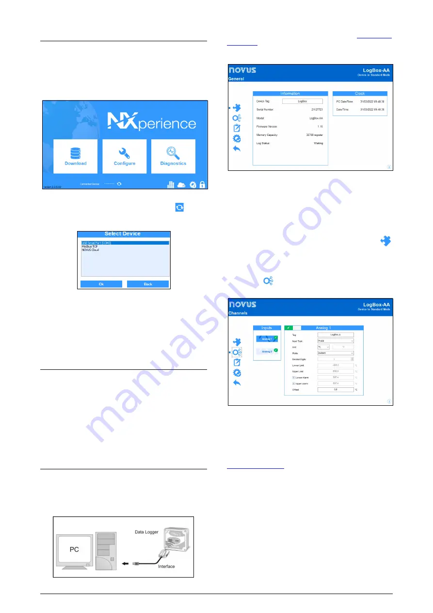
Afterwards, if you need to return to this screen, just click on the
button.
CHANNELS
By clicking the
button, you can access the configuration fields of
the logger analog channels:
Figure 7 –
Analog channel
The configuration fields for the analog channels are the following:
Tag
: Set of up to 8 characters that allows you to identify the variable.
Input Type
: Allows you to define the signal applied to the analog
input of the logger. The list shows all the available input options. The
option adopted must be according to the jumper configuration (see
item).
Unit
: Allows you to define the unit to be used for the measured
variable.
Mode:
Allows you to define the recording mode:
Instant:
The device performs a measurement. The value is
recorded at each acquisition "Interval".
Medium:
The device periodically takes ten measurements over
each acquisition "Interval". The recorded value is the average of
these measurements.
Minimum:
The device periodically takes ten measurements over
each acquisition "Interval". The recorded value corresponds to the
smallest measurement.
Maximum:
The device periodically takes ten measurements over
each acquisition "Interval". The recorded value corresponds to the
largest measure.


