N1020 Temperature Controller
NOVUS AUTOMATION
6/8
DETERMINATION OF PID PARAMETERS
The determination (or tuning) of the PID control parameters in the
controller can be carried out in an automatic way and auto-adaptative
mode. The automatic tuning is always initiated under request of the
operator, while the auto-adaptive tuning is initiated by the controller
itself whenever the control performance becomes poor.
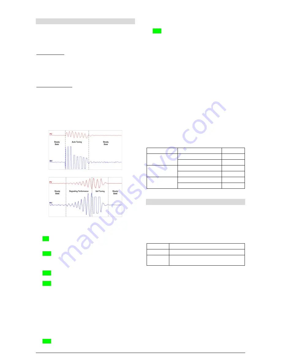
Automatic Tuning: In the beginning of the automatic tuning the
controller has the same behavior of an ON/OFF controller, applying
minimum and maximum performance to the process. Along the
tuning process the controller's performance is refined until its
conclusion, already under optimized PID control. It begins
immediately after the selection of the options FAST, FULL, RSLF or
TGHT, defined by the operator in the parameter ATUN.
Auto-adaptative Tuning: Is initiated by the controller whenever the
control performance is worse than the one found after the previous
tuning. In order to activate the performance supervision and auto-
adaptative tuning, the parameter ATUN must be adjusted for SELF,
RSLF or TGHT. The controller's behavior during the auto-adaptative
tuning will depend on the worsening of the present performance. If
the maladjustment is small, the tuning is practically imperceptible for
the user. If the maladjustment is big, the auto-adaptive tuning is
similar to the method of automatic tuning, applying minimum and
maximum performance to the process in ON/OFF control.
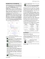
Fig. 04 – Example of auto tuning
Fig. 05 – Example of auto-adaptative tuning
The operator main select through the ATUN parameter, the desired
tuning type among the following options:
•
OFF
: The controller does not carry through automatic tuning or
auto-adaptative tuning. The PID parameters will not be
automatically determined nor optimized by the controller.
•
FAST
: The controller will the process automatic tuning one
single time, returning to the OFF mode after finishing. The tuning
in this mode is completed in less time, but not as precise as in
the FULL mode.
•
FULL
: The same as the FAST mode, but the tuning is more
precise and slower, resulting in better performance of the P.I.D.
•
SELF
: The performance of the process is monitored and the
auto-adaptative tuning is automatically initiated by the
controller whenever the performance poorer.
After a tuning level, the controller starts collecting data from the
process for determining the performance benchmark that will
allow evaluate the need for future tunings. This phase is
proportional to the process response time and is signaled by the
flashing TUNE indication on the display. It is recommended not
to turn the controller off neither change the SP during this
learning period.
It is recommended not to turn the controller off neither change the
SP during this learning period.
•
rSLF
: Accomplishes the automatic tuning and returns into the
SELF mode. Typically used to force an immediate automatic
tuning of a controller that was operating in the SELF mode,
returning to this mode at the end.
•
TGHT
: Similar to the SELF mode, but in addition auto-adaptative
tuning, it also executes the automatic tuning whenever the
controller is set in RUN=YES or when the controller is turned on.
Whenever the parameter ATUN is altered by the operator into a
value different from OFF, an automatic tuning is immediately
initiated by the controller (if the controller is not in RUN=YES, the
tuning will begin when it passes into this condition). The
accomplishment of this automatic tuning is essential for the correct
operation of the auto-adaptative tuning.
The methods of automatic tuning and auto-adaptative tuning are
appropriate for most of the industrial processes. However, there may
be processes or even specific situations where the methods are not
capable to determine the controller's parameters in a satisfactory
way, resulting in undesired oscillations or even taking the process to
extreme conditions. The oscillations themselves imposed by the
tuning methods may be intolerable for certain processes.
These possible undesirable effects must be considered before
beginning the controller's use, and preventive measures must be
adopted in order to assure the integrity of the process and users.
The AT signaling device will stay on during the tuning process.
In the case of PWM or pulse output, the quality of tuning will also
depend on the level time adjusted previously by the user.
If the tuning does not result in a satisfactory control, refer to Table 05
for guidelines on how to correct the behavior of the process.
PARAMETER
VERIFIED PROBLEM
SOLUTION
Proportional Band
Slow answer
Decrease
Great oscillation
Increase
Rate of Integration
Slow answer
Increase
Great oscillation
Decrease
Derivative Time
Slow answer or instability
Decrease
Great oscillation
Increase
Table 05 - Guidance for manual adjustment of the PID parameters
MAINTENANCE
PROBLEMS WITH THE CONTROLLER
Connection errors and inadequate programming are the most
common errors found during the controller operation. A final revision
may avoid loss of time and damages.
The controller displays some messages to help the user identify
problems.
MESSAGE
DESCRIPTION OF THE PROBLEM
----
Open input. No sensor o signal.
Err1
Err6
Connection and/or configuration errors. Check the wiring
and the configuration.
Other error messages may indicate hardware problems requiring
maintenance service.

