background image

N1020 Temperature Controller 

NOVUS AUTOMATION 

7/8 

CALIBRATION OF THE INPUT 
All inputs are factory calibrated and recalibration should only be done 

by qualified personnel. If you are not familiar with these procedures 

do not attempt to calibrate this instrument. 
The calibration steps are: 
a)


Configure the input type to be calibrated. 

b)


Enter in Calibration Level. 

c)


At the input terminals, apply a signal corresponding to a value 

slightly above the lower input limit. 

d)


Access the parameter 

inLC

. Using the   and   keys, adjust 

the display reading such as to match the  applied signal, then 

press the   key 

e)


At the input terminals, apply a signal corresponding to a value 

slightly below the upper input limit. 

f)


Access the parameter 

inkC

. Using the   and   keys, adjust 

the display reading such as to match the applied signal, then press 

the   key. 

g)


Return to the Operation level and check the calibration result. 

Note:  When checking the controller calibration with a Pt100 

simulator, pay attention to the simulator minimum excitation current. 

requirement, which may not be compatible with the 0.170 mA 

excitation current provided by the controller. 

 
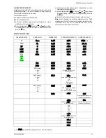
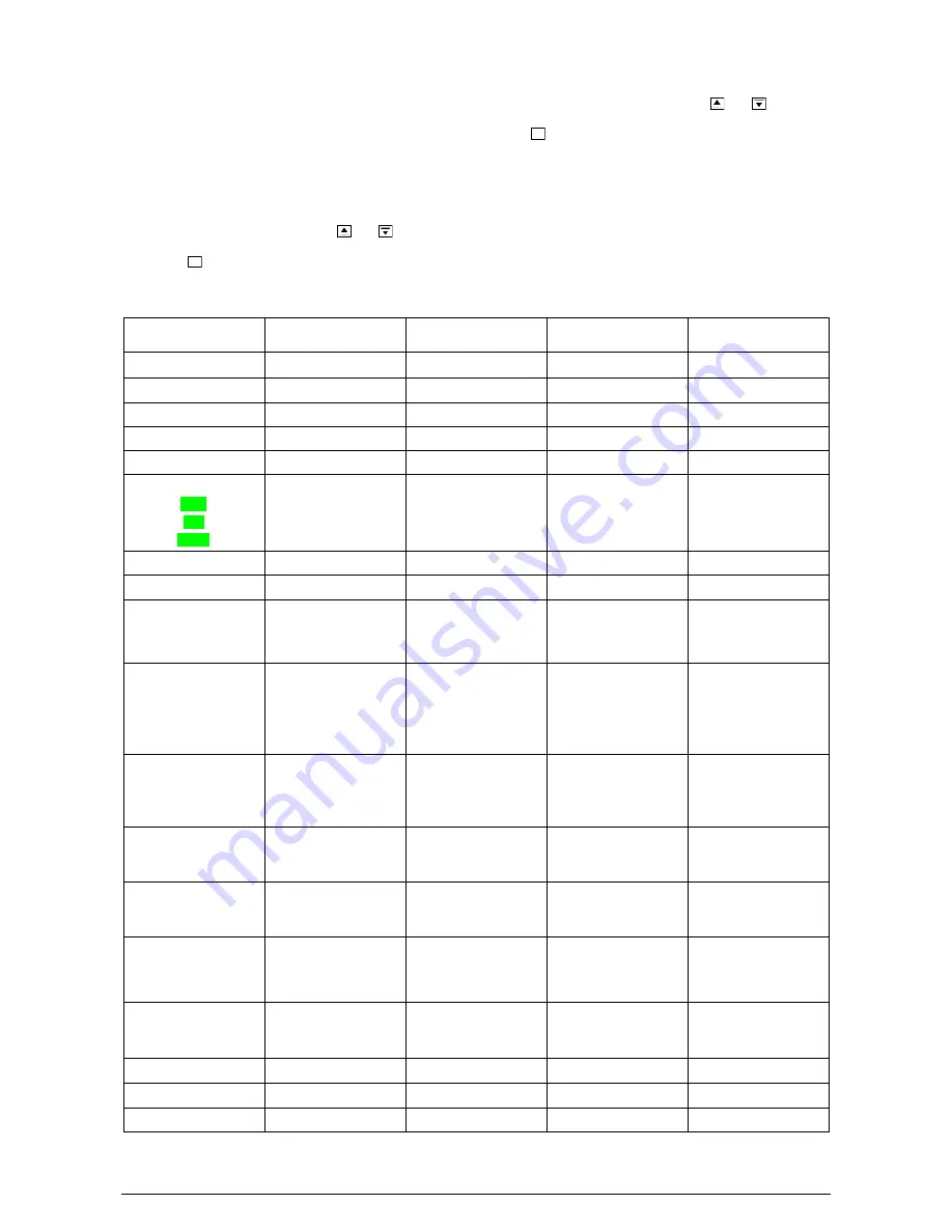
N1020 PARAMETER TABLE 

OPERATING LEVEL 

TUNING LEVEL 

ALARMS LEVEL 

CONFIGURATION LEVEL 

CALIBRATION LEVEL 

PV 

atvn


Fv.a1


Type 

Pass

 ( * )


Timer 

pb 

Fv.a2 

fltr 

(alib 

SP


ir 

Sp.a1


Dp.po 

In.L( 

T1me 

dt 

Sp.a2


vnI t 

In.k( 

Rate


(t


Bl.a1 

0ffs 

rstr 

RUN 

- YES 

- NO 

- F Key 

kyst 

Bl.a2 

Sp.ll 

ovll 


ACt 

Xy.a1 

Sp.xl 

ovkl 


sfst 

Xy.a2


T1me 

(j 


OUT1 (pulse) 

- Control 

- AL1 

- AL2 

A1.t1


Tm.en


(Enables the timer in the 

operating level) 

Pas.( 


OUT2 (relay 1) 

- Control 

- AL1 

- AL2 

A2.t1


T.str 

(starts Timer in operating level) 

- SP 

- RUN 

F key (reset) 

F key (on/off) 

Prot 


OUT3 (relay 2) 

- Control 

- AL1 
- AL2 

A2.t2


T.e.(.0 

YES  Disables the outputs 

(RUN=NO) 

NO – Doesn’t disable outputs 

Freq


flsh 


Rate


Snk 

Most significant digits of the 

instrument serial number 


rt.en


(shows the 

Rate


parameter in 

the operating level) 

Snl 

Least significant digits of the 

instrument serial number 


RUN 

- YES 

- NO 

F key 


rv.en


(shows the 

Rvn


parameter in 

the operating level) 


bavd 


prty 


Addr 


( * ) The 

PASS

 prompt precedes the parameters on the protected levels. 


Summary of Contents for N1020

Page 1: ...nsult the DEVICE MANAGER in the Windows CONTROL PANEL to identify the COM port that was assigned to the controller Consult the mapping of the MODBUS memory in the controller s communications manual an...

Page 2: ...the value of measured PV is above the value defined for alarm Setpoint SPA1 PV dif Alarm of Differential Value In this function the parameters SPA1 and SPA2 represent the deviation of PV in relation...

Page 3: ...ine trimming the PV indication to compensate for sensor errors Default value zero SERIAL COMMUNICATION For full documentation download the Registers Table N1020 for Serial Communication on our web sit...

Page 4: ...opriate for cooling Turns control output on when PV is above SP sfst Softstart SoftStart Function Time in seconds during which the controller limits the MV value progressively from 0 to 100 It is enab...

Page 5: ...fications carried out by the user ovll Output Low Limit Lower limit for the control output Minimum percentage value assumed by the control output when in automatic mode and in PID Typically configured...

Page 6: ...E indication on the display It is recommended not to turn the controller off neither change the SP during this learning period It is recommended not to turn the controller off neither change the SP du...

Page 7: ...tion with a Pt100 simulator pay attention to the simulator minimum excitation current requirement which may not be compatible with the 0 170 mA excitation current provided by the controller N1020 PARA...

Page 8: ...PR OUT1 Pulse OUT2 Relay B Digital Communication 485 Interface communication RS485 C Power Supply Nothing shown 100 240 Vac 48 240 Vdc 50 60 Hz 24V 12 24 Vdc 24 Vac SAFETY INFORMATION Any control sys...

Reviews: