N1040 Controller
NOVUS AUTOMATION
5/7
The master password is made up by the last three digits of the serial
number of the controller added to the number 9000. As an example,
for the equipment with serial number 07154321, the master
password is 9 3 2 1.
Controller serial number is displayed by pressing
for 5 seconds.
DETERMINATION OF PID PARAMETERS
During the process of determining automatically the PID parameters,
the system is controlled in ON/OFF in the programmed Setpoint. The
auto-tuning process may take several minutes to be completed,
depending on the system. The steps for executing the PID auto-
tuning are:
•
Select the process Setpoint.
•
Enable auto-tuning at the parameter “
Atvn
”, selecting
FAST
or
FULL
.
The option
FAST
performs the tuning in the minimum possible time,
while the option
FULL
gives priority to accuracy over the speed.
The sign TUNE remains lit during the whole tuning phase. The user
must wait for the tuning to be completed before using the controller.
During auto tuning period the controller will impose oscillations to the
process. PV will oscillate around the programmed set point and
controller output will switch on and off many times.
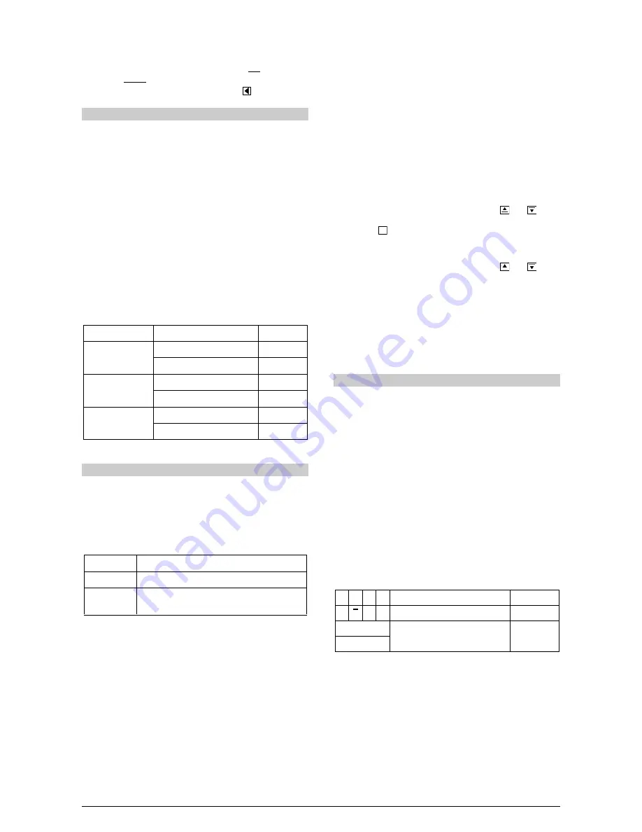
If the tuning does not result in a satisfactory control, refer to Table 05
for guidelines on how to correct the behavior of the process.
PARAMETER
VERIFIED PROBLEM
SOLUTION
Band Proportional
Slow answer
Decrease
Great oscillation
Increase
Rate Integration
Slow answer
Increase
Great oscillation
Decrease
Derivative Time
Slow answer or instability
Decrease
Great oscillation
Increase
Table 05 - Guidance for manual adjustment of the PID parameters
MAINTENANCE
PROBLEMS WITH THE CONTROLLER
Connection errors and inadequate programming are the most
common errors found during the controller operation. A final revision
may avoid loss of time and damages.
The controller displays some messages to help the user identify
problems.
MESSAGE
DESCRIPTION OF THE PROBLEM
----
Open input. No sensor or signal.
Err1
Err6
Connection and/or configuration problems.
Check the wiring and the configuration.
Other error messages may indicate hardware problems requiring
maintenance service.
CALIBRATION OF THE INPUT
All inputs are factory calibrated and recalibration should only be done
by qualified personnel. If you are not familiar with these procedures
do not attempt to calibrate this instrument.
The calibration steps are:
a) Configure the input type to be calibrated in the
type
parameter.
b) Configure the lower and upper limits of indication for the maximum
span of the selected input type.
c) Go to the Calibration Level.
d) Enter the access password.
e) Enable calibration by setting YES in
(alib
parameter.
f) Using an electrical signals simulator, apply a signal a little higher
than the low indication limit for the selected input.
g) Access the parameter “
inLC
”. With the keys and adjust
the display reading such as to match the applied signal. Then
press the key.
h) Apply a signal that corresponds to a value a little lower than the
upper limit of indication.
i) Access the parameter “
inLC
”. With the keys and adjust
the display reading such as to match the applied signal.
j) Return to the Operation Level.
k) Check the resulting accuracy. If not good enough, repeat the
procedure.
Note: When checking the controller calibration with a Pt100
simulator, pay attention to the simulator minimum excitation current
requirement, which may not be compatible with the 0.170 mA
excitation current provided by the controller.
SERIAL COMMUNICATION
The controller can be supplied with an asynchronous RS-485 digital
communication interface for master-slave connection to a host
computer (master).
The controller works as a slave only and all commands are started by
the computer which sends a request to the slave address. The
addressed unit sends back the requested reply.
Broadcast commands (addressed to all indicator units in a multidrop
network) are accepted but no reply is sent back in this case.
CHARACTERISTICS
•
Signals compatible with RS-485 standard. MODBUS (RTU)
Protocol. Two wire connection between 1 master and up to 31
(addressing up to 247 possible) instruments in bus topology.
•
Maximum connection distance: 1000 meters.
•
Programmable speed; 8 data bits; 1
stop
bit; selectable parity
(none);
The RS-485 signals are:
D1 D D + B Bi-directional data line.
Terminal 15
D0
D - A Bi-directional inverted data line.
Terminal 16
C
Optional connection that improves the
performance of the communication.
Terminal 17
GND
P
D:

