NOVUS AUTOMATION
1/7
N1040i Indicator
UNIVERSAL INDICATOR – INSTRUCTIONS MANUAL – V2.0x A
PRESENTATION
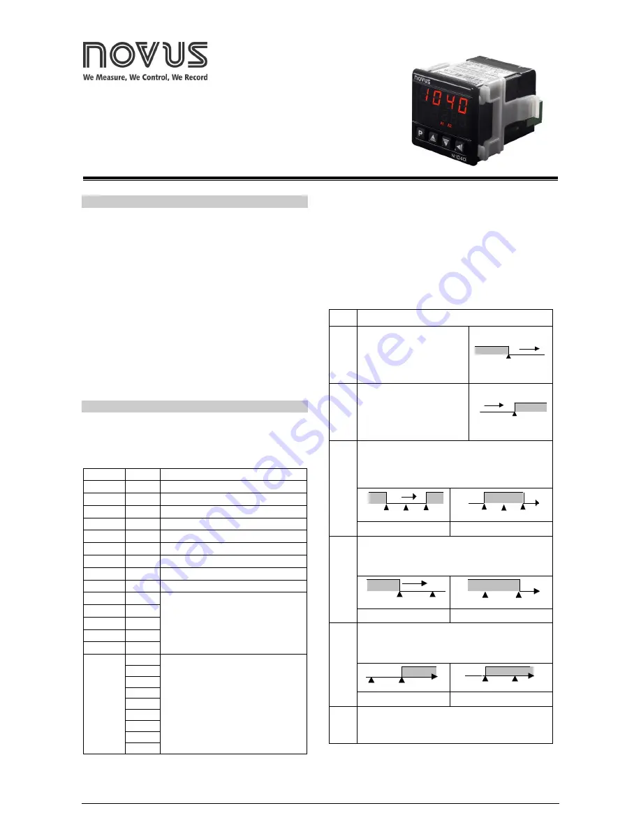
N1040i is a quite versatile process indicator. With a wide list of input
types - thermocouples, thermo-resistance, voltage and current – the
N1040i is capable of measuring the majority of the variables and
sensors encountered in industrial processes.
The configuration can be performed directly on the indicator or through
the USB interface. The
NConfig
software (free) is the configuration
management tool. Connected to the USB of a
Windows
computer, the
indicator is recognized as a serial communications port (COM) running
with a Modbus RTU protocol.
Through the USB interface, even if disconnected from the power
supply, the configuration performed in a piece of equipment can be can
be saved in a file and repeated in other pieces of equipment that
require the same configuration.
It also features various alarm functions, display offset, configuration
with password protection, serial communication, indication in degrees
Celsius (°C) or Fahrenheit (°F), among others.
FEATURES
SIGNAL INPUT (INPUT)
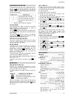
The input type to be used by the indicator is defined in the equipment
configuration.
Table 01
presents the input options available for the
user.
TYPE
CODE
RANGE OF MEASUREMENT
J
Tc j
Range: -110 to 950 ºC (-166 to 1742 ºF)
K
Tc k
Range: -150 to 1370 ºC (-238 to 2498 ºF)
T
Tc t
Range: -160 to 400 ºC (-256 to 752 ºF)
N
Tc n
Range: -270 to 1300 ºC (-454 to 2372 ºF)
R
Tc r
Range: -50 to 1760 ºC (-58 to 3200 ºF)
S
Tc s
Range: -50 to 1760 ºC (-58 to 3200 ºF)
B
Tc b
Range: 400 to 1800 ºC (752 to 3272 ºF)
E
Tc e
Range: -90 to 730 ºC (-130 to 1346 ºF)
Pt100
Pt
Range: -200 to 850 ºC (-328 to 1562 ºF)
0-20 mA
L0.20
Analog Linear Signal
Indication programmable from -1999 to
9999.
4-20 mA
L4.20
0–50 mV
L0.50
0-5 Vdc
L0.5
0-10 Vdc
L0.10
4-20 mA
NON
LINEAR
Lnj
Non Linear Analog Signal
Indication range according to the
associated sensor.
Ln k
ln t
ln n
ln r
ln s
ln b
ln E
Ln.Pt
Table 01
– Inputs Types
ALARMS
The 1040i can have none, one or two alarms. Each alarm present is
associated to one output with the same name (ALARM1 and ALARM2).
OUTPUT
ALARM1
- Relay SPDT. Available in terminals 10, 11 and
12 of the indicator.
OUTPUT
ALARM2
- Relay SPST-NA. Available in terminals 13 and
14 of the indicator.
The alarms can assume the functions described on
Table 02
.
off
Alarm off.
lo
Alarm of the Absolute Minimum
Value. It triggers when the
value of the
PV
is
below
the
value defined by the alarm
Setpoint (SPA1 or SPA2)
.
SPA1
PV
ki
Alarm
of
the
Absolute
Maximum Value. It triggers
when the value of the
PV
is
above
the value defined by the
alarm
Setpoint
.
SPA1
PV
dif
Alarm of the Differential Value. In this function the
parameters “
SPA1
” and “
SPA2
” represent errors
(difference) between the PV and one reference value
ALrF
.
ALrF
PV
ALrF+SPA1
ALrF
–SPA1
ALrF
PV
ALrF
– SPA1
alarme
ALrF + SPA1
alarme
SPA1 positive
SPA1 negative
difl
Alarm of the Minimum Differential Value. It triggers when
the value of the PV is
below
the point defined by:
ALrF-SPA1
(using alarm 1 as an example).
ALrF
PV
ALrF
– SPA1
ALrF
PV
ALrF
– SPA1
SPA1 positive
SPA1 negative
difk
Alarm of the Maximum Differential Value. It triggers when
the value of the PV is
above
the point defined by:
ALrF+SPA1
(using alarm 1 as an example).
ALrF
PV
ALrF + SPA1
ALrF
PV
ALrF + SPA1
SPA1 positive
SPA1 negative
ierr
Alarms of the Sensor Break (Sensor
Break Alarm
). It is
activated when the Input presents problems such as
interrupted sensor, bad connection, etc.
Table 02
– Alarm Functions
Note
: The figures are also valid for Alarm 2 (SPA2).


