N1040i Indicator
NOVUS AUTOMATION
5/7
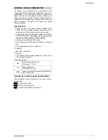
CONFIGURATION PROTECTION
The indicator allows the protection of the configuration performed by
the user, not allowing improper modifications. The parameter
Protection
(
PROt
), in the Calibration level, determines the
protection strategy to be adopted, limiting the access to the levels,
according to the table below.
Protection Level
Protected Levels
1
Only the Calibration level is protected.
2
Input and Calibration levels are protected.
3
Alarms, Input and Calibration levels are
protected.
Table 03
– Levels of Protection of the Configuration
ACCESS PASSWORD
The protected levels, when accessed, request the user to provide the
Access Password
for granting permission to change the
configuration of the parameters on these levels.
The prompt
PASS
precedes the parameters on the protected levels.
If no password is entered, the parameters of the protected levels can
only be visualized.
The Access Password is defined by the user in the parameter
Password Change
(
PAS.(
), present in the Calibration Level.
The
factory default for the password code is 1111
.
PROTECTION OF THE ACCESS PASSWORD
The protection system built into the indicator blocks for 10 minutes
the access to protected parameters after 5 consecutive frustrated
attempts of guessing the correct password.
MASTER PASSWORD
The Master Password is intended for allowing the user to define a
new password in the event of it being forgotten. The Master
Password doesn’t grant access to all parameters, only to the
Password Change
parameter (
PAS(
). After defining the new
password, the protected parameters may be accessed (and
modified) using this new password.
The master password is made up by the last three digits of the serial
number of the indicator
added
to the number 9000.
As an example, for the equipment with serial number 07154321, the
master password is 9 3 2 1.
The indicator serial number can be obtained by pressing
for 5
seconds.
MAINTENANCE
PROBLEMS WITH THE INDICATOR
Connection errors and inadequate programming are the most
common problems en ountered during the indicator operation. A final
revision can avoid loss of time and damages.
The indicator displays some messages to help the user identify the
problems.
MESSAGE
DESCRIPTION OF THE PROBLEM
----
Open input. Without sensor or signal.
Err1
Err6
Connection and/ or configuration problems. Check
the wiring and the configuration.
Other error messages may indicate hardware problems requiring
maintenance service. When contacting the manufacturer, inform the
instrument serial number, obtained by pressing the key
for more
than 3 seconds.
INPUT CALIBRATION
All inputs are factory calibrated and recalibration should only be done
by qualified personnel. If you are not familiar with these procedures
do not attempt to calibrate this instrument.
The calibration steps are:
a)
Configure the type of input to be calibrated.
b)
Configure the lower and upper limits of indication for the
maximum span of the selected input type.
c)
At the input terminals inject a signal corresponding to a known
indication value a little above the lower display limit.
d)
Access the parameter “
inL(
”. With the keys
and
, f adjust
the display reading such as to match the applied signal. Then
press the
P
key.
e)
Inject a signal that corresponds to a value a little lower than the
upper limit of indication.
f)
Access the parameter “
ink(
”. With the keys
and
, adjust
the display reading such as to match the applied signal. Then
press the
P
key.
Note
: When checking the indicator calibration with a Pt100 simulator,
pay attention to the simulator minimum excitation current
requirement, which may not be compatible with the 0.170 mA
excitation current provided by the indicator.
ANALOG OUTPUT CALIBRATION
1.
Configure analog input for 0-20 mA retransmission (
retr
=
p.0.20
).
2.
Attach a milliamp meter to terminals 13 and 14.
3.
Enter Calibration Cycle.
4.
Access “
ovl(
” calibration parameter and press
followed by
.
5.
Using
or
Keys, set “
ovLC
” parameter to the same value
read in the milliamp meter
6.
Access “
ovk(
” calibration parameter and press
followed by
.
7.
Using
or
Keys, set “
ovkC
” parameter to the same value
read in the milliamp meter.
8.
Exit Calibration Cycle.
SPECIFICATIONS
DIMENSIONS
: ............................................................ 48 x 48 x 80 mm
Approximate Weight: ...............................................................75 g
POWER SUPPLY
: ......................... 100 to 240 Vac (±10 %), 50/60 Hz
Optional 24 V ...................... 12 a 24 Vdc / 24 Vac (-10 % / +20 %)
................................... 24 to 240 Vdc (±10 %) for model N1040i-F
Maximum consumption: ........................................................ 6 VA
ENVIRONMENTAL CONDITIONS
:
Operation Temperature: ................................................ 0 to 50 ºC
Relative Humidity:.................................................... 80 % @ 30 ºC
For temperatures above 30 ºC, reduce 3 % per ºC
Indoor use; Installation Category II, Pollution Degree 2; altitude <
2000 meters
INPUT
................................................................ According to
Table 01
Internal Resolution:...................................... 32767 levels (15 bits)
Display Resolution: ................................................ 0.1 / 1 (°C / °F)
Input reading rate: .......................................... up to 55 per second
Precision @ 25 °C: ....
J
,
K
,
T
,
E
: 0.25 % of the
span
0.1 °C / °F
.....................................
N
,
R
,
S
,
B
: 0.25 % of the
span
1 °C / °F
................................................................ Pt100: 0.2 % of the
span
..................... 4-20 mA, 0-50 mV, 0-5 V, 0-10 V: 0.2 % of the
span
Input impedance: ........ Pt100, thermocouples, 0-50 mV: > 10 M
................................................................. 0-5 V, 0-10 V: > 500 k
.............................................................................. 4-20 mA: 100
Measuring of the Pt100: ......................... 3 wire type, (
=0.00385)
With compensation of the cable length, max 50 meters,
excitation current of 0.170 mA.


