N1050 Controller
NOVUS AUTOMATION
2/8
PID AUTOMATIC MODE
For the Automatic mode, there are two different strategies of control:
PID control and ON/OFF control.
PID control has its action based on a control algorithm that takes into
account the deviation of PV with respect to SP, the rate of change of
PV and the steady state error.
On the other hand, the ON/OFF control (obtained when Pb=0)
operates with 0 % or 100 % of power, when PV deviates from SP.
The determination of the PID parameters
(
Pb
,
ir
and
Dt
) is
described in the item DETERMINATION OF PID PARAMETERS of
this manual.
CONTROL OUTPUT
The control strategy can be
ON/OFF
(when
PB
=
0.0
)
or
PID
. The
PID parameters can be automatically determined enabling the auto-
tuning function (
ATun
).
ALARM OUTPUT
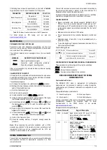
The controller contains 2 alarms that can be directed (assigned) to any
output channel. The alarm functions are described in
Table 02
.
off
Output is not used as alarm.
Lo
Alarm of Absolute Minimum
Value. Triggers when the
value of measured
PV
is
below
the value defined for
alarm
Setpoint
.
SPA1
PV
Hi
Alarm of Absolute Maximum
Value. Triggers when the
value of measured
PV
is
above
the value defined for
alarm
Setpoint
.
SPA1
PV
dif
Alarm of Differential Value. In this function the
parameters
SP.A1
and
SP.A2
represent the deviation
of PV in relation to the SP of CONTROL.
SP
PV
SP + SPA1
SP – SPA1
SP
PV
SV – SPA1
SV + SPA1
Positive SPA1
Negative SPA1
Dif.L
Alarm of Minimum Differential Value. It triggers when
the value of PV is
below
the defined point by (using
the Alarm 1 as example).
SP
PV
SP – SPA1
SP
PV
SP – SPA1
Positive SPA1
Negative SPA1
Dif.H
Alarm of Valor Maximum Differential Value. Triggers
when the value of PV is
above
the defined point by
(using Alarm 1 as example).
SP
PV
SP + SPA1
SP
PV
SP + SPA1
Positive SPA1
Negative SPA1
ierr
Alarms of the Sensor Break (Sensor
Break Alarm
). It is
activated when the Input presents problems such as
interrupted sensor, bad connection, etc.
r5
Event (
r
amp and
S
oak). Activated in a specific
segment of program.
Table 02
– Alarm functions
Note
: Alarm functions on
Table 02
are also valid for Alarm 2
(
SP.A2
).
Important note
: Alarms configured with the
ki
,
dif
, and
difk
functions also trigger their associated output when a sensor fault is
identified and signaled by the controller. A relay output, for example,
configured to act as a High Alarm (
ki
), will operate when the SPAL
value is exceeded and also when the sensor connected to the
controller input is broken.
INITIAL BLOCKING OF ALARM
The
Initial Blocking
option inhibits the alarm from being recognized
if an alarm condition is present when the controller is first energized
(or after a transition from run YES
NO). The alarm will be enabled
only after the occurrence of a non-alarm condition followed by a new
occurrence for the alarm.
The initial blocking is useful, for instance, when one of the alarms is
configured as a minimum value alarm, causing the activation of the
alarm soon upon the process start-up, an occurrence that may be
undesirable.
The initial blocking is disabled for the sensor break alarm function
ierr
.
SAFE OUTPUT VALUE WITH SENSOR FAILURE
Function that ensures that the control output is in a safe condition for
the process when an error in the sensor input is identified.
When a fault is identified in the sensor, the controller will determine
the percentage value set in the parameter
iE.ou
for the control
output. The controller will remain in this condition until the sensor
failure disappears. When in ON/OFF mode, the values for
iE.ou
are only 0 and 100%. With control in PID mode, any value between 0
and 100% will be accepted.
LBD FUNCTION – LOOP BREAK DETECTION
The parameter defines a time interval, in minutes, within which the
PV is expect to react to a control output signal. If the PV does not
react properly within the time interval configured in
Lbd.t
, the
controller interprets this as a control loop break and signals this
occurrence in the display.
A LBD event may be sent to any output channel. Simply configure
the LDB function to the desired output channel (OUT1 or OUT2): the
selected output will be activated when a LDB condition is detected.
When the
Lbd.t
parameter is programmed with 0 (zero), the LDB
function is disabled.
The LBD is useful in detecting system failures, such us defective
sensors or actuators, loads and power supply, among others.
OFFSET
Allows fine adjustments to the PV reading for compensation of
sensor error.
USB INTERFACE
The USB interface is used for CONFIGURING or MONITORING the
controller. The
NConfig
software must be used for the configuration.
It makes it possible to create, view, save and open configurations
from the equipment or files in your computer. The tool for saving and
opening configurations in files makes it possible to transfer
configurations between pieces of equipment and to make backup
copies. For specific models, the
NConfig
software also makes it
possible to update the firmware (internal software) of the controller
through the USB.
For MONITORING purposes you can use any supervisory software
(SCADA) or laboratory software that supports the MODBUS RTU
communication on a serial communications port. When connected to
the USB of a computer, the controller is recognized as a conventional
serial port (COM x). Use the
NConfig
software or consult the
DEVICE MANAGER in the Windows CONTROL PANEL to identify
the COM port that was assigned to the controller. Consult the
mapping of the MODBUS memory in the controller’s communications
manual and the documentation of your supervisory software to
conduct the MONITORING process.
Follow the procedure below to use the USB communication of the
equipment:
1.
Download the
NConfig
software from our website and install it on
your computer. The USB drivers necessary for operating the
communication will be installed together with the software.
2.
Connect the USB cable between the equipment and the
computer. The controller does not have to be connected to a

