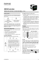
N1050 Controller
NOVUS AUTOMATION
3/8
power supply. The USB will provide enough power to operate the
communication (other equipment functions cannot operate).
3.
Open the
NConfig
software, configure the communication and
start recognition of the device.
The USB interface IS NOT SEPARATE from the
signal input (PV) or the controller’s digital inputs and
outputs. It is intended for temporary use during
CONFIGURATION and MONITORING periods. For
the safety of people and equipment, it must only be
used when the piece of equipment is completely
disconnected from the input/output signals. Using the
USB in any other type of connection is possible but
requires a careful analysis by the person responsible
for installing it. When MONITORING for long periods
of time and with connected inputs and outputs, we
recommend using the RS485 interface, which is
available or optional in most of our products.
OPERATION
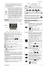
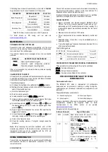
The controller’s front panel, with its parts, can be seen in the
Fig. 02
:
Fig. 02
- Identification of the parts referring to the front panel
Display:
Displays the measured variable, symbols of the
configuration parameters and their respective values/conditions.
Tx/RX Indicators:
Flashes when the controller exchanges data with
the RS-485 communication network.
AT Indicator:
On while the controller is in automatic tuning.
MAN Indicator:
On while the controller is in manual mode.
RUN Indicator:
On with control enabled (
RUN
=
YES
).
OUT Indicator:
Indicates the instantaneous state of the control
output(s).
A1 and A2 Indicators:
Indicate the occurrence of an alarm
condition.
°C / °F Indicators:
Identify the set temperature unit.
Key:
Key used to advance to successive parameters and
parameter cycles.
Increment Key and Decrement Key:
Keys used to change
the parameter values.
Tecla
: Keys used to retrocede parameters when in configuration
mode and performs special functions.
INITIALIZATION
When the controller is energized, the number of its current software
version will be displayed in the first 3 seconds, and then the value of
the measured process variable (temperature) will be displayed on the
upper display. The value of SP is displayed in the lower display. This
is the
Display Screen
.
To be used in a process, the controller needs to be preconfigured.
The configuration consists of the definition of each of the several
parameters presented. The user must understand the importance of
each parameter and, for each one, determine a valid condition or a
valid value.
The configuration parameters are gathered into groups of affinities,
called parameter cycles. The 6 parameter cycles are:
1 – Operation / 2 – Tuning / 3 – Programs / 4 – Alarms /
5 – Input / 6 – Calibration
The key gives access to the cycles and their parameters:
When you hold the key down, the controller will cycle from one
cycle to another every 2 seconds, displaying the first parameter of
each cycle:
PV
>>
atun
>>
Pr.tb
>>
fu.a1
>>
type
>>
pass
>>
PV
…
To enter the desired cycle, simply release the key when your first
parameter is displayed. To advance on the parameters of this cycle,
use the key with short beeps. To return parameters, use the
key.
Each parameter has its symbol displayed in the upper display. Its
respective value/condition is shown in the lower display.
Depending on the Configuration Protection adopted, the
PASS
parameter is displayed as the first parameter of the cycle where the
protection starts. See chapter Configuration Protection.
DESCRIPTION OF THE PARAMETERS
OPERATION CYCLE
PV + SP
PV Indication screen
. On the higher display
(white) the value of the measured variable (PV)
temperature is shown. On the lower display (green),
the control setpoint (SP) is shown.
CtrL
Control
Control Mode:
auto
- Means automatic control mode;
MaN
- Means manual control mode.
(Bumpless transfer between automatic and manual
control modes).
PV / MV
MV screen.
Displays the PV value in the upper
display and, in the lower display, displays the MV
value, in percentage, applied to the control output.
In Automatic Control mode, the value of MV can
only be displayed. In Manual Control mode, the
value of MV can be changed by the user.
To differentiate this screen from the PV+SP
screen, the value of MV blinks constantly.
Sp.a1
Sp.a2
Setpoint
Alarm
Alarm SP
. Value that defines the alarm activation
point. For the alarms set up with the functions of the
type
Differential
, these parameters define
deviations.
For the alarm function
i.err
, this parameter is not
used.
Parameters shown in this level only when enabled
in the parameters
sp1.E
and
sp2.E
.
E pr
Enable Program
Execution of Program
. Selects the ramp and
soak profile program to be executed.
0
- Does not execute program;
1 to 5
- Number of the program to be
executed.
With enabled outputs (
RUN
=
YES
), the program
starts right after the program is selected.
p.Seg
Program
Segment
Screen for indication only. When a ramp and soak
program is active, this parameter shows the number
of the segment under execution, from 1 to 4.
t.seg
Time
Segment
Screen for indication only. When a ramp and soak
program is in execution, it shows the remaining
time to the end of the current segment, in units of
time configured in the
Pr.tb
parameter.
RUN
Run
Enables control outputs and alarms.
YES
- Outputs enables;
No
- Outputs not enabled.

