Indicator N1500
NOVUS AUTOMATION
4/7
OPERATION
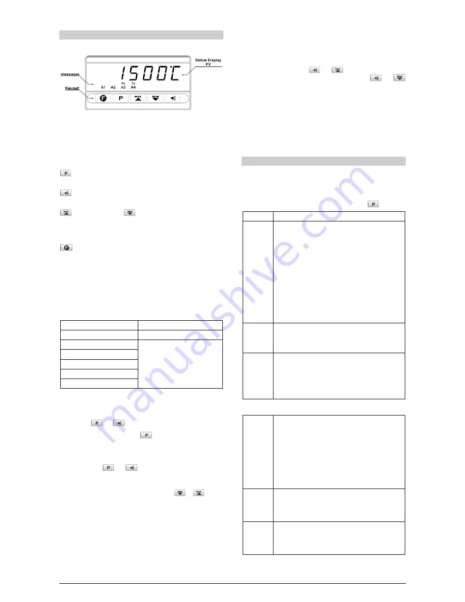
The front panel is shown below.
Fig. 10 - Front panel identification
Status Display: Shows the process variable (PV) and the
programming prompts.
Indicators A1, A2, A3 and A4: show active alarms.
Indicators Rx and Tx: indicate RS485 communication line is active.
PROGRAM key - This key is used to access different
displays with the programmable parameters of the device.
BACK key - This key is used to go back to the previous
parameter displayed in the menu level.
UP / MAX and
DOWN / MIN key – It is used to
increase and decrease parameters values. These keys are
also used to display maximum and minimum values stored
in memory.
FUNCTION key - This special function key is used for pre-
programmed functions as explained in the special function key
section of this manual.
The indicator requires that the internal parameters be properly
configured such as to fit the application need. These parameters are
the input type (T/C, Pt100, 4-20 mA, etc), alarms triggering points,
alarm functions, etc.
These parameters are divided in five levels (or groups) of parameters
which we will refer to as LEVELS.
LEVEL
ACCESS
1- Work
Free access
2- Alarms
Reserved access
3- Functions
4- Configuration
5- Customized Linearization
6- Calibration
Table 4 - Parameters Levels
The work level has free access. All other levels require a certain
combination of key strokes to be accessed. The combination is:
and
keys pressed simultaneously
Once within a level, just press
to move to the subsequent
parameters of this level. At the end of each level the display will go
back to the work level.
NOTE: In order to access the calibration level, however, it’s required
to press the keys
and
simultaneously for 10 seconds. The
first parameter in this level is presented (
In.LoC
) indicating that the
calibration level is enabled.
After reaching the intended prompt just press the
or
keys to
change this parameter accordingly. All changes are recorded in non-
volatile memory as we move to next prompt. After 25 seconds with no
key pressed the indicator will return to the measuring level (work level).
CONFIGURATION PROTECTION
As safety measure, parameter changes can be prevented by a
combination of keys, valid for each level. The protected parameters
can be inspected but not modified.
To protect a level press the
and
keys simultaneously for 3
seconds while in the level. To unlock the level, press
and
for 3 seconds.
The display will briefly flash confirming that the level was
successfully locked or unlocked.
For further protection, the keypad unlock operation can be disabled
by changing the position of an internal strap inside the indicator:
When PROT is OFF, the user is allowed to lock and unlock the levels
using the keypad as explained above. If PROT is ON, the levels
lock/unlock operation is disabled.
PROGRAMMING THE INDICATOR
WORK LEVEL
This is the first level. At power up the indicator will display the Process
Variable (PV). The alarm triggering points are also displayed at this level
(alarm Setpoints). To advance in this level simply press
.
SCREEN
PROMPT PARAMETER DESCRIPTION
8.8.8.8.8.
PV Measurement. Shows the measured variable. For
Pt100 or thermocouples the display will show the absolute
temperature value.
For 4-20 mA, 0-50 mV, 0-5 V and 0-10 mV inputs the
display shows the values defined in the “
in.LoL
” and
“
in.kiL
” parameters.
With the hold function programmed the display shows the
frozen variable and alternates with the message “
koLd
”.
Likewise, with Peak Hold function programmed the high
limit is displayed with the “
P.koLd
” prompt alternately.
Should any fault situation occur the indicator will display an
error message which can be identified at item 10 of this
manual.
Al.ref
Differential Alarm Reference Value - This prompt is
shown only when there is an alarm programmed with
differential function. This value is used as a reference for
differential alarms triggering.
Sp.al1
Sp.al2
Sp.al3
Sp.al4
Alarms Set Points 1, 2, 3 and 4 - Defines the operation
point of each alarm programmed with “
Lo
” or “
ki
”
functions.
When an alarm is programmed with a differential function,
the alarm setpoint value represents the deviation value of
the alarm relative to the reference
Al.ref
.
ALARM LEVEL
fV.al1
fV.al2
fV.al3
fV.al4
Alarm Function - Defines functions for the alarms 1, 2, 3
and 4.
oFF
: Alarm off
iErr
: Broken or Shorted Sensor
Lo
: Low value
ki
: High value
DiF.Lo
: Differential low
DiF.Hi
: Differential high
DiF.ov
: Differential outside the range
DiF.in
: Differential within range
Ky.al1
Ky.al2
Ky.al3
ky.al4
Alarm Hysteresis
This is the difference from the measured value to the point
where the alarm is turned ON and OFF.
Bl.al1
Bl.al2
Bl.al3
bl.al4
Alarm Blocking
Should any alarm condition occur, the alarms can be
individually disabled when energizing the indicator.


