Indicator N1500G
NOVUS AUTOMATION
4/6
Within a certain cycle just press
to go to the following
parameters. At the end of each cycle the display will go back to the
work cycle.
At the desired prompt just press the
or
key to
change this
parameter accordingly.
All changes are recorded in non-volatile memory as we move to next
prompt. After 25 seconds with no key pressed the indicator will return
to the measuring cycle (work cycle).
7.1.
CYCLE PROTECTION
The values of parameters of a certain cycle can be protected against
non-authorized users.
The protected parameters can still be viewed but can not be
changed.
To protect a cycle just press the
and
keys for 3 seconds at
the beginning of the referred cycle. To unlock this cycle (allow
changes in parameters), press the keys
and
for 3
seconds.
The display will briefly blink confirming that the locking or
unlocking of the cycle.
8.
PROGRAMMING THE INDICATOR
8.1.
WORK CYCLE
This is the first and main cycle. At power up the indicator will display
the Process Variable (PV). The alarm setpoints are also displayed at
this cycle. To run through this cycle just press the
key.
Whenever an alarm is set with differential function the respective
alarm setpoint is blocked (
SP.AL1
SP.AL1
SP.AL1
SP.AL1
,
SP.AL2
SP.AL2
SP.AL2
SP.AL2
, ...) and the display
shows “
diF
diF
diF
diF
” to advise the operator that this is a configuration
parameter and that the respective deviation value must be
programmed at the Alarms Cycle. The “
AL.rEF
AL.rEF
AL.rEF
AL.rEF
” prompt will be
displayed showing the reference value for the alarm with differential
function.
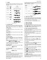
SCREEN
PARAMETER DESCRIPTION
8.8.8.8.8.
8.8.8.8.8.
8.8.8.8.8.
8.8.8.8.8.
Measure
Shows the measured variable. For Pt100
or thermocouples the display will show the absolute
temperature value.
For 4-20 mA, 0-50 mV and 0-5 V inputs the display
shows the values defined in the “
in.LoL
in.LoL
in.LoL
in.LoL
” and
“
in.HiL
in.HiL
in.HiL
in.HiL
” prompts.
With the
hold
function programmed the display
shows the frozen variable and alternates with the
message “
HoLd
HoLd
HoLd
HoLd
”.
Likewise, with
Peak
Hold
function programmed the
high limit is displayed with the “
P.HoLd
P.HoLd
P.HoLd
P.HoLd
” prompt
alternately.
Should any fault situation occur the indicator will
display an error message which can be identified at
item 10 of this manual.
Al.ref
Al.ref
Al.ref
Al.ref
Differential Alarm Reference Value
- This prompt
is shown only when there is an alarm programmed
with differential function.
Sp.al1
Sp.al1
Sp.al1
Sp.al1
Sp.al2
Sp.al2
Sp.al2
Sp.al2
Set Points of Alarms 1 and 2
- Defines the
operation point of each alarm programmed with “
Lo
Lo
Lo
Lo
”
or “
Hi
Hi
Hi
Hi
” function.
Note: When the alarms are programmed with
differential function, the alarm setpoint cannot be
changed at this cycle and a “
diF
diF
diF
diF
” message will be
shown. The SP differential (deviation) value is set at
the Alarm Cycle.
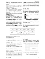
8.2.
ALARM CYCLE
fV.al1
fV.al1
fV.al1
fV.al1
fV.al2
fV.al2
fV.al2
fV.al2
Alarm
Function
- Defines the alarms 1, 2, 3 and 4
function, as defined in item 4.1
oFF
oFF
oFF
oFF
: Alarm off
iErr
iErr
iErr
iErr
: Broken or Shorted Sensor
Lo
Lo
Lo
Lo
: Low value
Hi
Hi
Hi
Hi
: High value
DiFL
DiFL
DiFL
DiFL
: Differential low
DiFH
DiFH
DiFH
DiFH
: Differential high
DiF
DiF
DiF
DiF
: Differential
Df.al1
Df.al1
Df.al1
Df.al1
Df.al2
Df.al2
Df.al2
Df.al2
Differential SP for Alarms 1 and 2
- Defines the
deviation value from the alarm setpoint in relation to
the Reference Value defined in the “
ALdiF
ALdiF
ALdiF
ALdiF
” prompt.
Note: This value cannot be changed at this cycle for
alarms with non-differential function and the “
AbS
AbS
AbS
AbS
” is
then displayed.
Ky.al1
Ky.al1
Ky.al1
Ky.al1
Ky.al2
Ky.al2
Ky.al2
Ky.al2
Alarm Hysteresis
This is the difference from the measured value to the
point where the alarm is turned ON and OFF.
Bl.al1
Bl.al1
Bl.al1
Bl.al1
Bl.al2
Bl.al2
Bl.al2
Bl.al2
Alarm Blocking
Should any alarm condition occur, each alarm can
be disabled when energizing the indicator. Refer to
item 4.3.
Al1t1
Al1t1
Al1t1
Al1t1
Al1t2
Al1t2
Al1t2
Al1t2
Al2t1
Al2t1
Al2t1
Al2t1
Al2t2
Al2t2
Al2t2
Al2t2
Time Alarms
The user can set delayed or sequential alarms as
shown in table 3 by defining times T1 and T2.
To disable this function just set zero for T1 and T2.
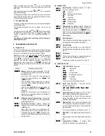
8.3.
FUNCTION CYCLES
f.fvnc
f.fvnc
f.fvnc
f.fvnc
F KEY FUNCTION
- Options are:
oFF
oFF
oFF
oFF
- Key no used.
Ho
Ho
Ho
Hold
ld
ld
ld
- Hold PV
AL.oFF
AL.oFF
AL.oFF
AL.oFF
-
Alarm disabled
rESEt
rESEt
rESEt
rESEt
-
Resets Peak and Valley
PHoLd
PHoLd
PHoLd
PHoLd
-
Peak Hold
tArE
tArE
tArE
tArE
- Tare zeroing
These functions are described in item 5.2.
Dig.in
Dig.in
Dig.in
Dig.in
Digital Input Function
- The same function
available for the
F
key:
oFF
oFF
oFF
oFF
-
Hold
Hold
Hold
Hold
-
AL.o
AL.o
AL.o
AL.oFF
FF
FF
FF
-
rESEt
rESEt
rESEt
rESEt
-
PHoLd
PHoLd
PHoLd
PHoLd
-
tArE
tArE
tArE
tArE
Refer to item 5.2.
filtr
filtr
filtr
filtr
Input Digital Filter
- Adjustable from 0 to 20, this is
used to reduce instability of the measured value.
0 means the filter is off and 20 means maximum
filtering. The higher the filter value the lower is the
measured value response.
ofset
ofset
ofset
ofset
Display Offset
- This a value which is added to the
PV to offset any measurement deviation or sensor
error. The offset is shown directly in the programmed
engineering unit.
For °F measurements the null reference is at 32 °F.
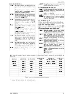
bavd
bavd
bavd
bavd
Baud Rate
- Serial digital communication speed in
bps
.
Programmable: 1200, 2400, 4800, 9600 and 19200
bps.
Adres
Adres
Adres
Adres
Communication Address
- A number which
identifies the instrument in a multidrop network.


