NOVUS AUTOMATION
6/6
9.
DIGITAL COMMUNICATION
The indicator can be supplied with an asynchronous RS-485 digital
communication interface for master-slave connection to a host
computer (master).
The indicator works as a slave only and all commands are started by
the computer which sends a request to the slave address. The
addressed unit processes the command and sends back the answer.
Broadcast commands (addressed to all indicator units in a multidrop
network) are accepted but no response is generated.
9.1.
CHARACTERISTICS
-
RS-485 compatibility with two-wire bus from the host to up to 31
slaves in a multidrop network topology.
-
Up to 247 units can be addressed by the MODBUS RTU protocol.
-
Maximum network distance: 1200 m.
-
Time of indicator disconnection: Maximum of 2 ms after the
delivery of the last byte.
-
Communication signals electrically isolated from the rest of the
instrument.
-
Baud rate: 1200, 2400, 4800, 9600, 19200, 38400 or 57600 bps.
-
Number of data bits: 8, without parity or even parity
-
Number of stop bits: 1
-
Time to start response transmission: 100 ms maximum delay after
acknowledging the command.
-
Protocol: MODBUS (RTU)
9.2.
RS485 INTERFACE: ELECTRICAL CONNECTION
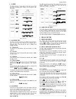
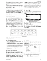
The RS-485 signals are: D1 = D: Bidirectional data line
D0 =
D:
Inverted bidirectional data line
C = GND: Optional connection. Improves
communication performance for
long cable runs.
REDUCED REGISTERS TABLE FOR SERIAL
COMMUNICATION
COMMUNICATION PROTOCOL
The MOSBUS RTU slave is implemented. All configurable
parameters can be accessed for reading or writing through the
communication port. Broadcast commands are supported as well
(address 0).
The available Modbus commands are:
01 – Read Coils
05 – Write Single Coil
03 - Read Holding Register
06 - Write Single Register
HOLDING REGISTER TABLE
Follows a description of the usual communication registers. For full
documentation download the
Registers Table for Serial
Communication
in the N1500G section of our website –
www.novusautomation.com
.
All registers are 16 bit signed integers
.
Address Parameter
Register Description
0000
PV
Read: process variable.
Write: not allowed.
Range: the minimum value is in
inlol
inlol
inlol
inlol
seted and the maximum value is in
inkil
inkil
inkil
inkil
seted an the decimal point
position depends of
dppos
dppos
dppos
dppos
.
0003
PV
Read: normalized Process Variable.
Write: not allowed.
Maximum range: 0 to 62000.
0004
Display
Value
Read: current display value.
Write: current display value.
Maximum range: -31000 to 31000.
The range depends of the showed
display.
10.
PROBLEMS WITH THE INDICATOR
Connection errors or improper configuration will result in
malfunctioning of the indicator. Carefully revise all cable connections
and programming parameters before operating the unit.
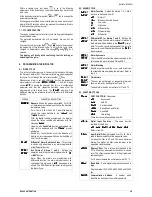
Some error messages will help the user identify possible problems.
Message
Possible Problem
VVVVV
VVVVV
VVVVV
VVVVV
Measured value is above the programmed
sensor or input signal limit.
nnnnn
nnnnn
nnnnn
nnnnn
Measured value is below the programmed sensor
or input signal limit.
-----
-----
-----
-----
Open input. No sensor is connected or the
sensor is broken.
Err 1
Err 1
Err 1
Err 1
Pt100 cable resistance is too high or the sensor
is badly connected.
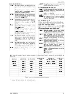
Different messages other than the ones above should be reported to
the manufacturer. Please inform the serial number if this should
occur. the serial number can be viewed at the display by pressing the
BACK
key for about 3 seconds.
The software version of the instrument can be viewed at the time the
unit is powered. The instrument might display false error messages
when wrongly programmed or when connected to a sensor for which
it was not programmed.
11.
WARRANTY
Warranty
conditions
are
available
on
our
website
www.novusautomation.com/warranty
.


