EN 9
1
2
3
4
5
6
7
8
9
10
GENERAL INFORMATION
These are the mounting instructions for the product shown on the cover. Carefully read these instructions before installation
and commissioning. It is recommended to have one or more qualified persons carry out the installation only.
Carefully remove the content from the packaging and check the materials. Do not use sharp knives to open the packaging.
In case of damage, immediately contact your dealer.
INSTALLATION
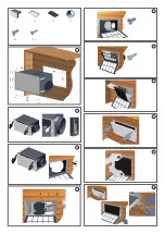
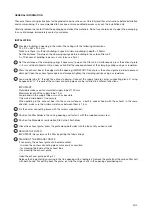
Provide a building-in opening in the wall or the ceiling with the following dimensions:
D1 x D2 = 487 x 255 mm
Make sure there is sufficient building-in space: minimum building-in depth = 295mm
Set the distance ‘A’ between the clamping springs before building in the carbon filter unit:
A = Thickness of building-in panel + 5 mm (also see fig. 5)
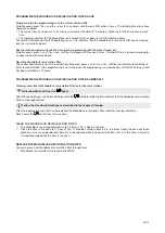
Set the distance of the clamping spring, if necessary: to open the filter unit, simultaneously press the exhaust grate
+/- 2 mm with both hands until you hear a click. Set the required distance of the clamping springs using a screwdriver.
Press the exhaust box at the edges into the opening. IMPORTANT: Do not press the exhaust grate in order to prevent
damage!! Open the exhaust grate again and manually tighten the clamping springs using a screwdriver.
Lead supply tube ‘B’ through the exhaust opening. Connect the supply tube to corner connecting piece ‘A’ using
bungee cord ‘C’. If required, the corner connecting piece can be installed in 3 different directions.
IMPORTANT:
Preferably make use of an insulated supply tube Ø 150 mm.
Maximum length of the supply tube: 10 m
Avoid bends in the supply tube as much as possible.
Only make ‘wide bends’ if necessary.
When building in the exhaust box into the same surface as a built-in cooker hood with the exhaust in the same
direction, make sure the minimum distance between them is 1.5 m.
Fix the corner connecting piece with the screws supplied (6x).
Position the filter holder in the casing opening and fasten it with the supplied screws (6x).
Position the Monoblock recirculation filter in the filter holder.
Close the exhaust grate: press the grate along both sides into the lock until you hear a click.
REMOVE THE FILTER
IMPORTANT: Never remove the filter by pulling the fabric lining!
DISMOUNT THE EXHAUST GRATE
If necessary, the exhaust grate can be dismounted:
- to make the corner connecting piece more easily accessible
- for cleaning the inside of the exhaust box
- for cleaning the exhaust grate
- ...
Open the exhaust grate (see fig. 3).
Release the hinge shaft by pressing in the free opening with a toothpick. Remove the grate from the carbon filter unit
with both hands. For putting back the grate, just clip the hinge shafts in the openings provided again.
Summary of Contents for 841.400
Page 2: ...1x 1x 1x 1x 6x 6x 1 2 3 4 5 6 7 8 9 10 ...
Page 11: ......

