23
24
3.3 Method to increase the effective radius of detecting charged
circuits
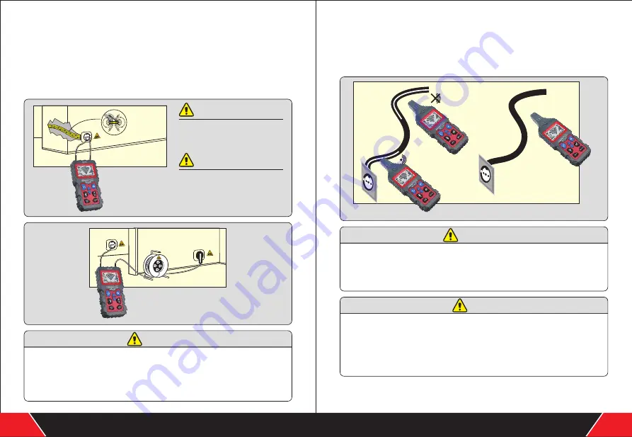
When the transmitter is directly connected to the phase line and neutral line, the signals
are conducted on two parallel circuits (as shown in Fig.3-3-1), so the twisting of circuits
may sometimes cause signals to counteract each other, leading to an effective radius of
0.5m at most . In order to eliminate this effect , the connection must be as shown in
Fig.3-3-2, where the loop line uses a separate cable to increase the effective radius to
over 2.5m, and loop lines with longer distances can be provided by the cable reel
(see Fig.3-3-2).
When connecting charged circuits
to the transmitter, please do abide
by the safety instructions.
Pay attention to the distance
between the transmitter and the
circuit to be detected, in order to
clearly determine the circuit
through signals.
1. In the process of detecting the circuit, the stronger the signal displayed on the
digital tube of the detector, the closer the cable detected by the detector.
2. Adjust the transmitting power of the transmitter to adapt to different radiuses of
detection.
3. Select the manual mode on the receiverand select suitable receiving sensitivity
to precisely locate the circuit.
3.4 Identify voltage in the grid and search for breakages in the
circuit
Preconditions:
The circuit must be charged with AC voltage;
※
The measurement must be conducted according to Fig.3-4;
※
Set the transmitter to "Grid Voltage Identification" mode (namely the UAC mode).
※
1.The AC signals detected by the transmitter in UAC mode only show that whether
the circuit is charged, and the precise measurement of voltage should be done
through the voltmeter function of the transmitter.
2.When searching for the ends of multiple power lines, it is necessary to connect
each line to the phase line separately.
1.This application does not need the transmitter. (Unless you want to use the
voltmeter function of the transmitter to precisely measure the voltage in the
circuit)
2.The signal strength columns displayed on the transmitter and the signal tone
frequency are related to the voltage in the circuit to be detected and the distance
to the circuit. The higher the voltage and the shorter the distance to the circuit, the
more the columns displayed and the higher the signal tone frequency.
Fig 3-3-1
Fig 3-3-2
Fig 3-4
Your excellent helper in measuring instruments
.
Your excellent helper in measuring instruments
.
WARNING
CAUTIONS
CAUTIONS
CAUTIONS
HINTS


