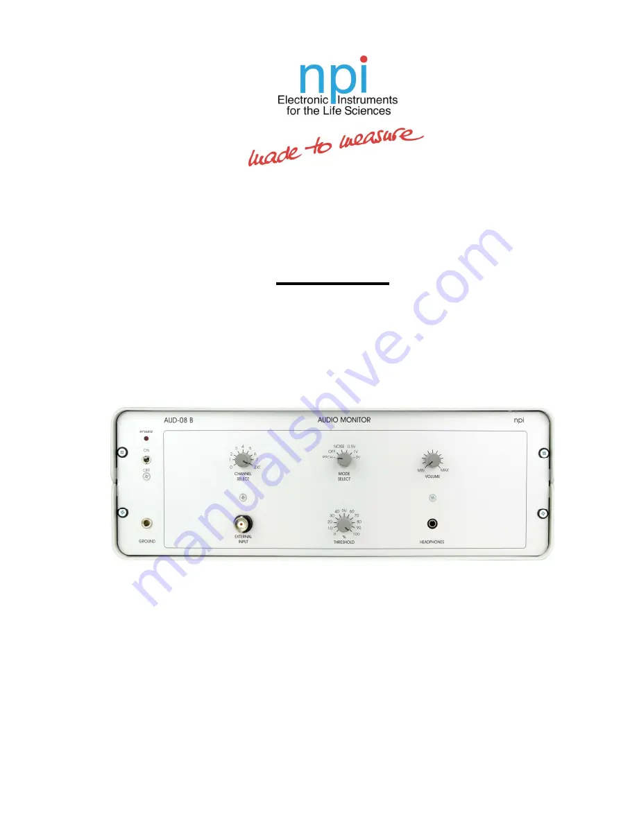
background image


OPERATING INSTRUCTIONS AND 

SYSTEM DESCRIPTION FOR THE 

AUD-08 B 

AUDIO MONITOR 


VERSION 1.1


npi 2014 


npi electronic GmbH, Bauhofring 16, D-71732 Tamm, Germany 

Phone +49 (0)7141-9730230; Fax: +49 (0)7141-9730240 

support@npielectronic.com; http://www.npielectronic.com 

Summary of Contents for AUD-08 B

Page 1: ...SYSTEM DESCRIPTION FOR THE AUD 08 B AUDIO MONITOR VERSION 1 1 npi 2014 npi electronic GmbH Bauhofring 16 D 71732 Tamm Germany Phone 49 0 7141 9730230 Fax 49 0 7141 9730240 support npielectronic com h...

Page 2: ...____ ___________________________________________________________________________ version 1 1 page 2 Table of Contents 1 Safety Regulations 3 2 AUD 08 B 4 2 1 Components 4 2 2 System Description 4 2 3...

Page 3: ...is to be operated only at 115 230 Volt 60 50 Hz AC Please check for appropriate line voltage before connecting any system to mains Always use a three wire line cord and a mains power plug with a prot...

Page 4: ...which it is connected via the system bus The signal that is used for audio monitoring is the 10 fold amplified DC signal This signal is not high or lowpass filtered or further amplified independent of...

Page 5: ...r position 3 CHANNEL SELECT rotary switch 9 position switch for selecting the channel to be monitored Position 0 7 correspond to the input channels from the EXT 02 B in the system EXT is the signal fr...

Page 6: ...THRESHOLD in of the value set by INPUT MODE switch 4 0 5 V 1 V 2 V For example if the INPUT MODE switch 4 is set to 2 V and the THRESHOLD potentiometer is set to 80 the resulting THRESHOLD for monitor...

Page 7: ...2 4 Description of the Rear Panel Figure 2 AUD 08 B rear panel view 1 SYSTEM BUS connector see also chapter 2 5 50 pin connecter providing power lines and data lines for connection of the AUD 08 B to...

Page 8: ...ve 1 x AUD 08 B 1 x REL 08 B The order in which the devices are chained up is not important Since it is a bus system all positions are treated equally Channel addresses When using monitoring devices R...

Page 9: ...on 1 1 page 9 3 Technical Data AUDIO MODE PITCH NOISE THRESHOLD selected by rotary switch with OFF position THRESHOLD RANGE and FINE control range 0 5 V 1 V or 2 V max INPUT BNC connector impedance 1...

Reviews: