

AUD-08 B User Manual
_______________________________________________________________________________________________________________
___________________________________________________________________________
version 1.1
page 5
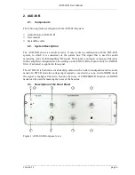
In the following description of the front panel elements, each element has a number that is
related to that in Figure 1. The number is followed by the name (in uppercase letters) written
on the front panel and the type of the element (in lowercase letters). Then, a short description
of the element is given.
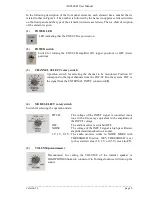
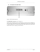
(1)
POWER LED
LED indicating that the EXT-02 B is powered on.
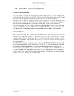
(2)
POWER switch
Switch for turning the EXT-02 B amplifier ON (upper position) or OFF (lower
position).
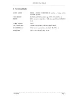
(3)
CHANNEL SELECT rotary switch
9-position switch for selecting the channel to be monitored. Position 0-7
correspond to the input channels from the EXT-02 B in the system. EXT. is
the signal from the EXTERNAL INPUT connector (#8).
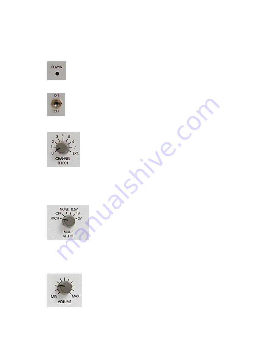
(4)
MODE SELECT rotary switch
Switch for selecting the operation mode:
PITCH:
The voltage of the INPUT signal is converted into a
tone with a frequency equivalent to the amplitude of
the INPUT voltage.
OFF:
The audio monitor is switched OFF.
NOISE:
The voltage of the INPUT signal is high pass filtered,
amplified and transduced to a sound.
2 V, 1 V, 0.5 V: The audio monitor works in NOISE MODE with
THRESHOLD function. 100% THRESHOLD is set
to the selected value (2 V, 1 V or 0.5 V) (see also #7).
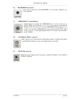
(5)
VOLUME potentiometer
Potentiometer for setting the VOLUME of the internal speaker or
HEADPHONES linked to connector #6. Turning clockwise will turn up the
sound.


