background image


OPERATING INSTRUCTIONS AND 

SYSTEM DESCRIPTION FOR THE 
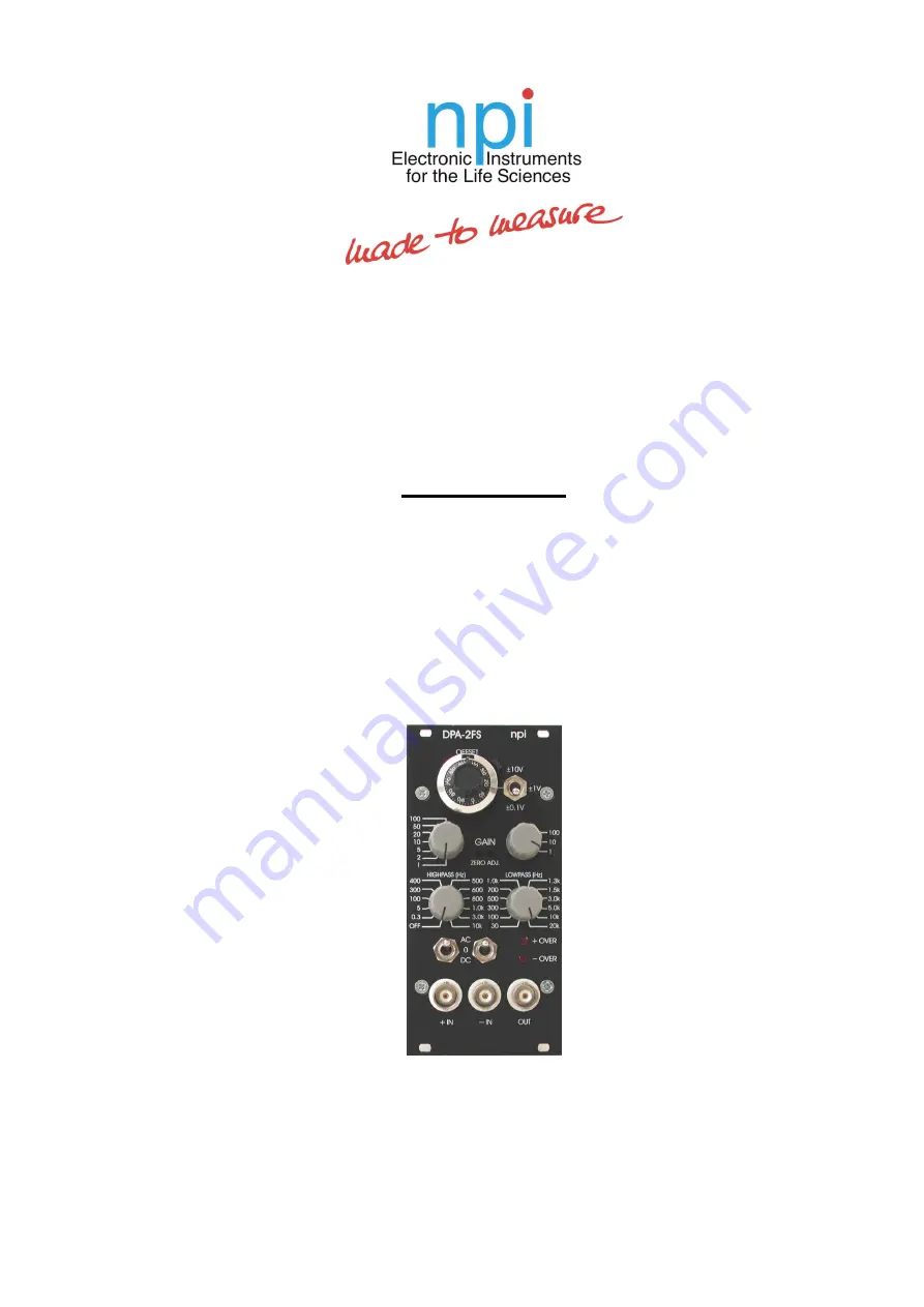
DPA-2FS 

DIFFERENTIAL AMPLIFIER / 

FILTER MODULE 

FOR EPMS SYSTEMS 


VERSION 2.0 

npi 2015 


npi electronic GmbH, Bauhofring 16, D-71732 Tamm, Germany 

Phone +49 (0)7141-9730230; Fax: +49 (0)7141-9730240 

support@npielectronic.com; http://www.npielectronic.com 

Summary of Contents for DPA-2FS

Page 1: ...FOR THE DPA 2FS DIFFERENTIAL AMPLIFIER FILTER MODULE FOR EPMS SYSTEMS VERSION 2 0 npi 2015 npi electronic GmbH Bauhofring 16 D 71732 Tamm Germany Phone 49 0 7141 9730230 Fax 49 0 7141 9730240 support...

Page 2: ...S E 07 Housing 4 2 5 EPMS 03 5 2 6 PWR 03D 5 2 7 System Grounding 6 EPMS 07 EPMS 03 6 EPMS E 07 6 2 8 Technical Data 6 EPMS 07 EPMS E 07 and EPMS H 07 6 EPMS 07 and EPMS H 07 6 EPMS E 07 6 EPMS 03 6 3...

Page 3: ...efore connecting any system to mains Always use a three wire line cord and a mains power plug with a protection contact connected to ground protective earth Before opening the cabinet unplug the instr...

Page 4: ...ems are shipped with the EPMS 07 housing EPMS 07 cabinet with built in power supply Mains cord Fuse 2 A 1 A slow inserted Front covers Figure 1 Left front view of empty EPMS 07 housing In order to avo...

Page 5: ...wer supply unit the power switch and the fuse are located at the rear of the housing see Figure 2 right 2 6 PWR 03D The external power supply PWR 03D is capable of driving up to 3 EPMS E housings Each...

Page 6: ...to the SYSTEM GROUND SIGNAL GROUND on the rear panel of the instrument see Figure 4 The chassis can be linked to PROTECTIVE EARTH by connecting it to the PWR 03D with the supplied 6 pole cable and by...

Page 7: ...nce is 10 M Thus the module can be used for direct recording of bioelectric signals e g from peripheral nerves Using the differential input configuration common mode signals and noise are removed allo...

Page 8: ...DPA 2FS User Manual version 2 0 page 8 3 4 Description of the Front Panel and Operation Figure 5 DPA 2FS front panel view...

Page 9: ...OFFSET potentiometer 10 turn potentiometer for compensating for a DC OFFSET Note The overall OFFSET compensation is the product of the reading of both controls Important Position 5 of the OFFSET poten...

Page 10: ...LEDs indicating that the DPA 2FS exceeds its linear range 10 V 7 OUT connector BNC connector providing the conditioned signal 8 9 IN IN connector BNC connectors for connecting the input signal The in...

Page 11: ...i 15 1641 1645 Huemmeke M Eysel U T Mittmann T 2004 Lesion induced enhancement of LTP in rat visual cortex is mediated by NMDA receptors containing the NR2B subunit J Physiol 559 875 882 Schulz D Hust...

Page 12: ...1 1 V or 10 V set by toggle switch HIGHPASS Filter single pole attenuation 6 dB octave corner frequencies Hz 0 3 5 100 300 400 500 600 800 1k 3k 10k LOWPASS Filter single pole attenuation 6 dB octave...

Reviews: