DPA-2FS User Manual
version 2.0
page 6
2.7.
System Grounding
EPMS-07/EPMS-03
The 19" cabinet is grounded by the power cable through the ground pin of the mains
connector (= protective earth). In order to avoid ground loops the internal ground is isolated
from the protective earth. The internal ground is used on the BNC connectors or GROUND
plugs of the modules that are inserted into the EPMS-07 housing. The internal ground and
mains ground (= protective earth) can be connected by a wire using the ground plugs on the
rear panel of the instrument. It is not possible to predict whether measurements will be less or
more noisy with the internal ground and mains ground connected. We recommend that you try
both arrangements to determine the best configuration.
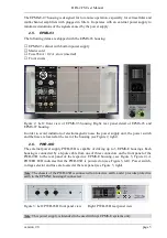
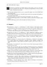
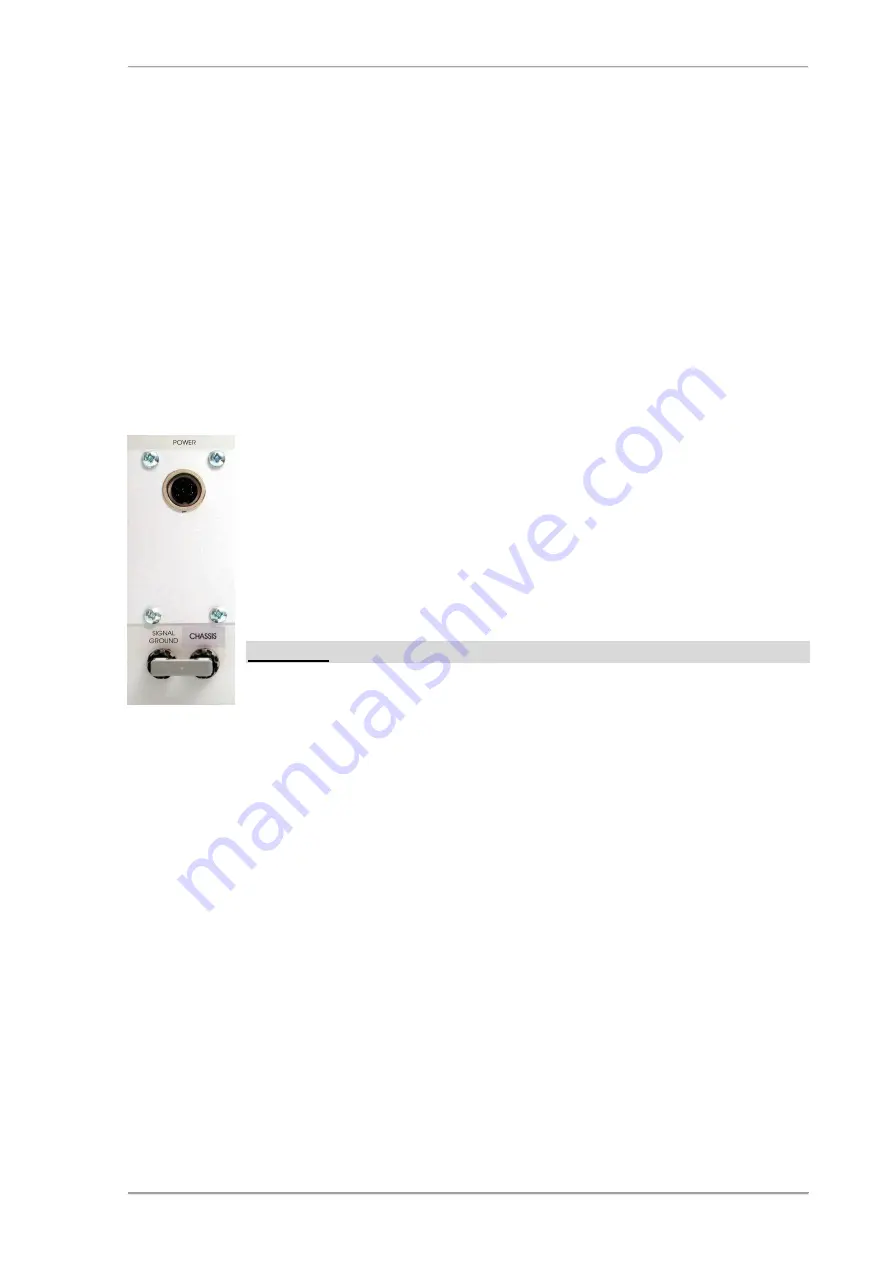
EPMS-E-07
The 19" cabinet is connected to the CHASSIS connector at the rear panel. It
can be connected to the SYSTEM GROUND (SIGNAL GROUND) on the
rear panel of the instrument (see Figure 4).
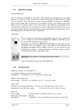
The chassis can be linked to PROTECTIVE EARTH by connecting it to the
PWR-03D with the supplied 6-pole cable and by interconnecting the
GROUND and PROTECTIVE EARTH connectors on the rear panel of the
PWR-03D (see Figure 3). Best performance is generally achieved without
connection of the chassis to protective earth.
Important: Always adhere to the appropriate safety measures.
Figure 4: Rear panel connectors of the EPMS-E-07
2.8.
Technical Data
EPMS-07, EPMS-E-07 and EPMS-H-07
19” rackmount cabinet, for up to 7 plug-in units
Dimensions:
3U high (1U=1 3/4” = 44.45 mm), 254 mm deep
EPMS-07 and EPMS-H-07
Power supply: 115/230 V AC, 60/50 Hz, fuse 2 A / 1 A slow, 45-60 W
EPMS-E-07
External power supply (PWR-03D) 115/230 V AC, 60/50 Hz, fuse 1.6/0.8 A, slow
Dimensions of external power supply:
(W x D x H) 225 mm x 210 mm x 85 mm
EPMS-03
Power supply:
115/230 Volts AC, 60/50 Hz, fuse 0.4 A / 0.2 A slow
Maximum current supply: 500 mA
Dimensions:
3U high (1U=1 3/4” = 44.45 mm), 254 mm deep, 265 mm wide


