background image

EXT-10C User Manual 

___________________________________________________________________________ 


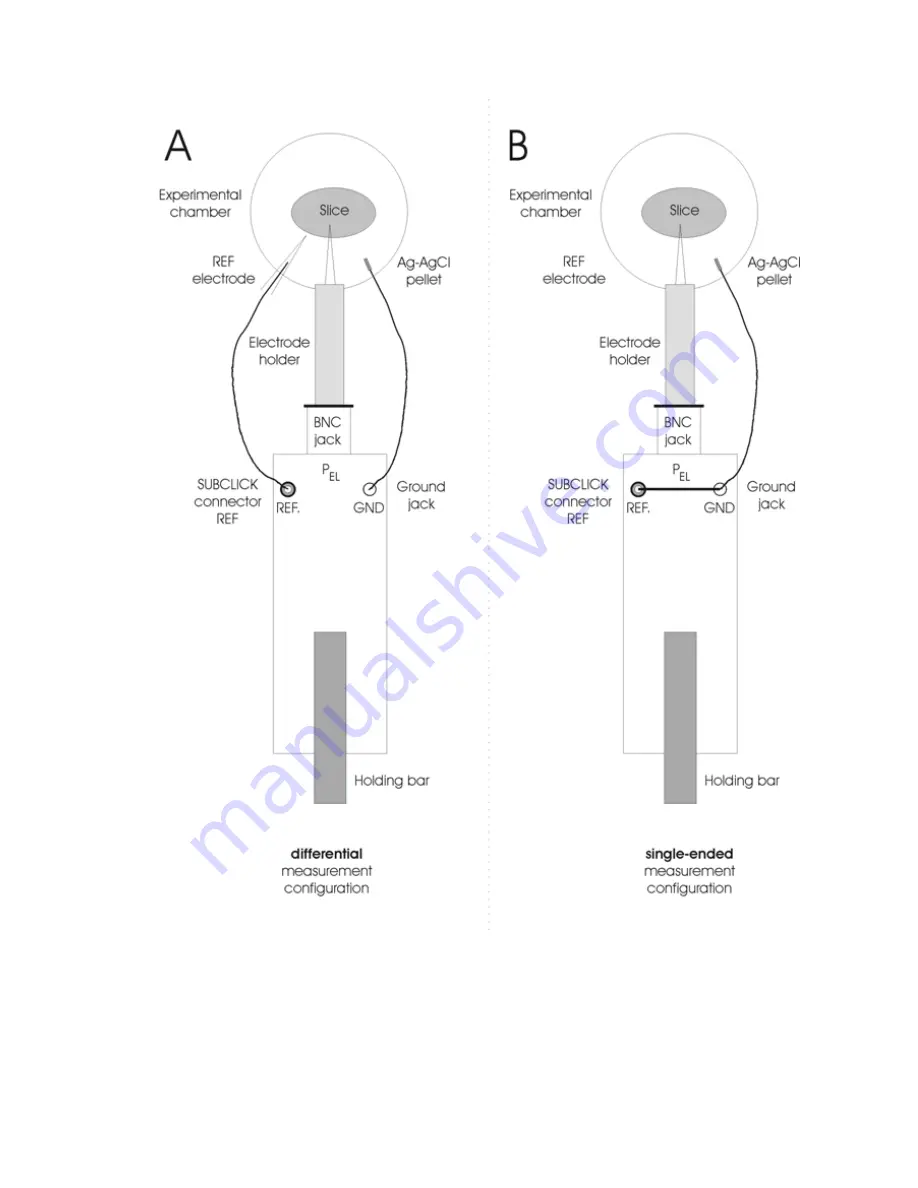
Figure 4: headstage connections, A: differential measurement, B: single-ended measurement 


___________________________________________________________________________ 
version 1.5 


page 10 

Summary of Contents for EXT-10C

Page 1: ...ION FOR THE EXT 10C EXTRACELLULAR AMPLIFIER MODULE FOR EPMS SYSTEMS VERSION 1 5 npi 2005 npi electronic GmbH Hauptstrasse 96 D 71732 Tamm Germany Phone 49 0 7141 601534 Fax 49 0 7141 601266 support np...

Page 2: ...ents 1 Safety Regulations 3 2 EPMS 07 Modular Plug In System 4 2 1 Components of the EPMS 07 Housing 4 2 2 General System Description Operation 4 2 3 System Grounding 5 2 4 Technical Data 5 3 EXT 10C...

Page 3: ...only at 115 230 Volt 60 50 Hz AC Please check for appropriate line voltage before connecting any system to mains Always use a three wire line cord and a mains power plug with a protection contact conn...

Page 4: ...e plug in units are connected to power by a bus at the rear panel The plug in units must be kept in position by four screws M 2 5 x 10 The screws are important not only for mechanical stability but al...

Page 5: ...internal ground is used on the BNC connectors or GROUND plugs of the modules that are inserted into the EPMS 07 housing The internal ground and mains ground protective earth can be connected by a wire...

Page 6: ...dstage with a holding bar The EXT 10C has a differential input with high input resistance for minimizing noise and the incoming signal can be compensated for offset and capacity of the microelectrode...

Page 7: ...d by the name in uppercase letters written on the front panel and the type of the element in lowercase letters Then a short description of the element is given 1 HEADSTAGE connector The HEADSTAGE cabl...

Page 8: ...l cancellation of the OFFSET 6 OVER OVER LEDs LEDs that indicate if the amplifier 10 below it s positive or negative limit 10 V The linear range of the amplifier is 12 V 7 OFFSET potentiometer 10 turn...

Page 9: ...l input that minimizes noise pick up Differential means that the signal for the amplifier is the difference between the positive PEL and negative REF input of the headstage This results in canceling o...

Page 10: ..._________________________________________________________ Figure 4 headstage connections A differential measurement B single ended measurement _________________________________________________________...

Page 11: ...ter maze performance exploratory activity inhibitory avoidance and hippocampal plasticity in aged superior and inferior learners Eur J Neurosci 16 2175 2185 Kettenmann H Grantyn R eds 1992 Practical E...

Page 12: ...t range 12 V into 1 k 1 V into 50 load Output AC selectable gain x100 x1k x10k Output range 12 V into 1 k 1 V into 50 load corner frequency 10 Hz Offset compensation 10 turn potentiometer 100 mV Poten...

Reviews: