-
25
-
CHECKING THE HYDRAULIC FLOW AT RATED
PRESSURE
3. Determine Relief Valve Pressure and Oil Flow.
Measure flow and pressure with the flow meter. Adjust the load valve to zero
restriction. Warm up the hydraulic system of the excavator to normal operating
temperature. Set engine throttle to maximum. Press hammer foot switch. Turn in
the loading valve knob and record the pressure and flow at regular intervals on
graph paper. Record pressure on one axis of the graph and flow on the other.
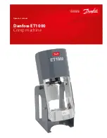
Increase pressure until relief setting is reached. This is the circuit flow chart. Refer
to hammer specification chart for correct flow at rated pressure for each hammer.
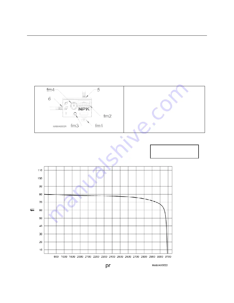
fm1. Load
Valve
fm2. Flow/Temperature
Display
fm3. Flow/Temperature
Switch
fm4. Pressure
Gauge
5
. Out
6
. In
Typical flow meter with pressure loading valve.
FLOW VS. PRESSURE CHART
TYPICAL EXAMPLE
fl FLOW
(GPM)
pr PRESSURE
(PSI)


