background image


- 15 -

LUBRICATION 

CORRECT GREASE FOR HYDRAULIC HAMMERS 

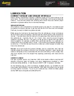
NPK HAMMER GREASE 

NPK now offers hammer grease specially formulated to meet severe job requirements.  
The grease is available in three different temperature ranges - 350°, 500°, and 2000°. 
All are compatible with Autolube systems. 

Universal Plus

 and 

Super Duty

 are lithium soap based products that resists washout 

and contain NPK-10 additive for surface protection in friction effected areas. 

Chisel Paste

 is an aluminum complex soap base with 12% graphite and copper 

additives for extreme operating conditions. 


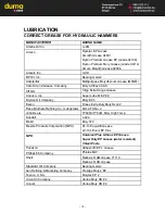
UNIVERSAL PLUS 

350 deg 

NPK PART 

NO. 

14 OZ. CARTRIDGE  G000-1010
120 LB. KEG 

G000-1020

35 LB. PAIL 

G000-1030

400 

LB

. DRUM 

G000-1040


SUPER DUTY 

500 deg 

NPK PART 

NO. 

14 OZ. CARTRIDGE  G000-1011
120 LB. KEG 

G000-1021

35 LB. PAIL 

G000-1031

400 LB. DRUM 

G000-1041


CHISEL PASTE 

2000 deg 

NPK PART 

NO. 

14 OZ. CARTRIDGE  G000-1050


AUTOLUBE SYSTEMS 

An automatic greasing system is recommended 
to reduce hammer tool and tool bushing wear.  
The NPK AUTOLUBE System is designed to 
automatically provide a continuous supply of 
grease to the hammer tool and tool bushing – 
increasing tool and tool bushing life by reducing 
wear.  The AUTOLUBE pump is capable of 
pumping EP2 grease in cold weather.  The pump 
output is adjustable according to the 
requirements of the hammer model and to 
compensate for tool bushing wear. 
 
NPK hammer models GH1, GH2/GHS2, GH3 
and GH4 have a connection port (26) located in the impact spacer for an automatic 
greasing system, (GH4 shown). 
 
Refer to the NPK AUTOLUBE Instruction Manual for details.  


29 – Grease Line, 30 – Grease Fitting 

Summary of Contents for GH06

Page 1: ...H06 GHS2 GH07 GH3 GH1 GH4 GH2 GH6 Copyright 2009 NPK Construction Equipment Inc www npkce com H050 9640A 03 09 doc 03 09 Use Genuine NPK Parts 7550 Independence Drive Walton Hills OH 44146 5541 Phone...

Page 2: ...MMER 19 DAILY START UP PROCEDURE 19 OPERATION 20 SAFE OPERATING INSTRUCTIONS 20 OPERATING TECHNIQUES PRECAUTIONS 21 ROUTINE INSPECTION AND MAINTENANCE 26 WEEKLY INSPECTION 27 TOOLS 28 STANDARD TOOLS 2...

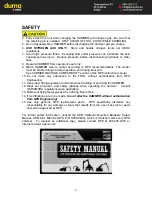
Page 3: ...le to the operator while operating the hammer STAY CLEAR PRESSURE VESSEL GAS PRESSURE and TOOL SHARPENING decals are installed on all NPK hammer models Keep them clean and visible NPK will provide dec...

Page 4: ...e NPK instruction manual 10 Do not make any alterations to the TOOL without authorization from NPK Engineering 11 Use proper lifting equipment and tools when handling or servicing the HAMMER 12 Wear e...

Page 5: ...best value available This comprehensive operator s manual contains instructions for operating and maintaining NPK HYDRAULIC HAMMERS This manual includes helpful information for obtaining the full pot...

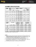
Page 6: ...d void Warranties Please consult NPK Engineering for specific detailed information CARRIER WEIGHT lbs kg HAMMER MOUNTING RECOMMENDED RANGE MODEL STYLE lb kg GH06 Excavator 2 200 4 400 1 000 2 000 Skid...

Page 7: ...5 1650 115 2150 150 350 24 405 28 GH07 4 9 15 35 1500 105 2000 140 350 24 405 28 GH1 7 13 25 50 1750 120 2250 155 350 24 405 28 GH2 GHS2 7 17 25 65 2250 160 2750 190 350 24 405 28 GH3 12 26 45 100 190...

Page 8: ...HAMMER CONTROL VALVE NPK uses two general types of control systems depending upon the carrier model 1 CONTROL SYSTEM USING THE CARRIER AUXILIARY OR SPARE VALVE SECTION This type of installation utiliz...

Page 9: ...tem through the hose or tube connection when changing the hydraulic hammer with the bucket 3 Low oil level will cause heat build up resulting in deterioration of the oil Also it may cause cavitation d...

Page 10: ...into the hammer when re connected This again can cause damage 3 Most quick disconnects create a restriction in the circuit NPK Hammers are not back pressure sensitive but restrictions cause unnecessa...

Page 11: ...couplers are in good working condition Failure to inspect couplers may result in pieces from a damaged or failed coupler to be injected into the hammer or parts of the coupler returned to the machine...

Page 12: ...laying the hammer down 3 Cap the pressure and return lines on the carrier and connect the hammer whip hoses 4 Position the hammer DR horizontal on wood blocks t20 and remove boom pins m1 and m2 The h...

Page 13: ...the machine off 3 Grease the hammer until grease begins to come out around the tool and lower bushing 4 Grease hammer at least once an hour or install an NPK Autolube System See Correct Grease and Gre...

Page 14: ...e amount of grease and how often it must be applied An example would be that a particular hammer on a particular job requires half a tube of grease every 3 hours This would be the greasing schedule yo...

Page 15: ...M EP 2 Dryden Oil Company Moly EP 2 Exxon Ronex Extra Duty Moly NLGI 2 Fiske Brothers Refining Co Lubriplate MO LITH No 2 John Deere TY6333 TY6341 Moly High Temp Kendall L 424 Mobil Moly 372 Muscle Pr...

Page 16: ...DUTY 500 deg NPK PART NO 14 OZ CARTRIDGE G000 1011 120 LB KEG G000 1021 35 LB PAIL G000 1031 400 LB DRUM G000 1041 CHISEL PASTE 2000 deg NPK PART NO 14 OZ CARTRIDGE G000 1050 AUTOLUBE SYSTEMS An auto...

Page 17: ...olecules to cling together It is the ability of those molecules to resist separation under pressure between two metals and to hold these metal surfaces apart FRICTION The resistance to fluid flow in a...

Page 18: ...eping a supply of working fluid in a hydraulic system VIBRATION A quivering or trembling motion VISCOSITY Is the actual SAE weight of the product Example motor oils come in 10 20 30 40 50 and 15 40 SA...

Page 19: ...URE page 37 2 At idle raise the hammer off of the ground Place hammer vertical and activate the hammer circuit for 3 5 second intervals Continue for an additional 3 4 times to ensure that all the air...

Page 20: ...d the base machine in accordance with the machine manufacturer s instruction manual This is especially important during cold weather operation DAILY START UP PROCEDURE Operate the NPK HYDRAULIC HAMMER...

Page 21: ...ING DEBRIS FROM THE HAMMER TOOL POINT An impact resistant cab window or shield must be in place to protect the operator Do not use the hammer in a way as to cause rock etc to be thrown towards the cab...

Page 22: ...control lever or the foot pedal to start the NPK HYDRAULIC HAMMER Applying excessive force to the hammer will raise the carrier too high and jolt the operator when the material breaks Let the NPK HYDR...

Page 23: ...fulcrum of the tool This unnecessary added stress leads to the following problems 1 Premature bushing wear and or tool breakage 2 Breakage of tie rods 3 Breakage of bracket bolts When the tool binds f...

Page 24: ...s the tool penetration rate into the material and prevents overheating the tool tip DO NOT HAMMER CONTINU OUSLY IN THE SAME POSITION FOR MORE THAN 30 SECONDS If the tool cannot break or penetrate into...

Page 25: ...et and will move faster than expected DO NOT USE THE HAMMER OR BRACKET TO MOVE LARGE OBJECTS Do not use the hammer bracket for purposes other than for what is was intended AVOID OPERATING THE HAMMER W...

Page 26: ...hydraulic system The hammer can be modified for underwater operation contact the NPK Dealer for more information DO NOT SUBMERGE A HOT TOOL IN WATER The tip of the tool may be hot from operation Subm...

Page 27: ...nt The hammer must be in a vertical position with down force applied to push the tool all the way in This prevents grease from entering piston impact area Pump grease into hammer until grease is seen...

Page 28: ...for peening caused by excessive blank hammering If necessary grind edges smooth as shown in TOOL RETAINING PIN INSPECTION see page 32 The retaining pin must rotate freely 3 DEMOLITION TOOL Remove the...

Page 29: ...PC for GH6 Concrete breaking Highway construction General demolition ACCESSORY TOOLS SPECIALTY TOOL SHAPE APPLICATIONS FROST CUTTER Cross cut SX In Line SY for GH07 thru GH4 Edge of trenching Frost cu...

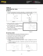
Page 30: ...4 See page 32 for additional retaining pin inspection and reconditioning Figure 3 RE INSTALLATION 1 Clean the retainer pin housing hole and retaining ring groove 2 Coat the surface of the tool with g...

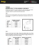
Page 31: ...AXIMUM CLEARANCE INCH mm d15 GH06 1 4 6 5 GH07 1 4 6 5 GH1 1 4 6 5 GH2 GHS2 1 4 6 5 GH3 1 4 6 5 GH4 1 4 6 5 GH6 3 8 10 Step 2 Remove the tool from the tool holder Measure the diameter d16 of the beari...

Page 32: ...AMETER INCH mm MAXIMUM BUSHING INSIDE DIAMETER INCH mm GH06 1 67 42 4 1 87 47 4 GH07 1 87 47 4 2 07 52 6 GH1 2 26 57 4 2 46 62 6 GH2 GHS2 2 61 66 4 2 82 71 6 GH3 3 01 76 4 3 21 81 6 GH4 3 40 86 4 3 61...

Page 33: ...ION Deformation may occur on the retaining pin in the tool contact area AN If this area is mushroomed the retaining pin may become difficult to remove Dress areas shown AN with a grinder HAMMER MODELS...

Page 34: ...to remove from the tool holder Dress with a grinder 2 Excessive blank hammering will cause chipping 16 in the retaining pin contact area 15 If neglected the chipping may reduce the life of the tool Dr...

Page 35: ...150 M10 65 85 N A N A GH07 M12 110 150 M10 65 85 N A N A GH1 M12 110 150 M10 65 85 N A N A GH2 GHS2 M12 110 150 M12 110 150 N A N A GH3 M16 270 365 M16 270 365 M8 30 40 GH4 M18 370 500 M16 270 365 M8...

Page 36: ...RGE THE HAMMER Exceeding the gas pre charge specifications can result in damaging hammer components The NPK WARRANTY does not cover failures resulting from exceeding the specified nitrogen gas pressur...

Page 37: ...is important to make sure that pin g14 bottom picture is not bent or damaged in any way If pin g14 is bent or damaged it may not be possible to check the charge in the hammer When the standard NPK gas...

Page 38: ...the hammer with the tool fully extended THE HAMMER MUST NOT BE RESTING ON THE POINT 2 Remove the charge valve cap M1 3 Turn the NPK charging adapter T handle g2 full counterclockwise 4 MODELS GH06 GH0...

Page 39: ...the gauge pressure with the NITROGEN GAS PRESSURE CHART see page 35 If the gas pressure is 25 psi 2 bar or more below specification proceed to NITROGEN GAS CHARGING PROCEDURE If the pressure is corre...

Page 40: ...apter g1 clockwise 6 Turn the handle g7 on the tank regulator counterclockwise to fully close 7 Open the valve g10 on the nitrogen tank by turning the T handle counterclockwise 8 Slowly adjust the reg...

Page 41: ...ing in the gas head that is different from all other NPK hydraulic hammers After removing the existing plug g12 the adapter g13 part no 30604100 is threaded onto the existing GH06 GH07 GH1 and GH2 GHS...

Page 42: ...e is encountered By turning the T handle g2 further the nitrogen gas pressure will be indicated on the pressure gauge g8 Stop turning the T handle when the gauge reads pressure Do not over tighten 7 L...

Page 43: ...ing your user name and password log into the system At the left of the next page click on REGISTRATION Complete the fields with an orange diamond next to them At the bottom of this area click the STAR...

Page 44: ...43 WARRANTY STATEMENT...

Page 45: ...ver with a waterproof tarp t21 not shown If the NPK HYDRAULIC HAMMER is not to be used for a long period of time months it is recommended the gas pressure be discharged M The tool HH should be removed...

Page 46: ...____________ SERIAL NUMBER _______________ NPK INSTALLATION KIT NUMBER ___________________________ CARRIER MANUFACTURER MODEL NUMBER SERIES SERIAL NUMBER DATE OF INSTALLATION _________________ DATE OF...

Page 47: ...Copyright 2009 NPK Construction Equipment Inc www npkce com H050 9640A 03 09 doc 03 09...

Page 48: ...Powered by TCPDF www tcpdf org...

Reviews: