0
.5.4 The angle measuring device 4 (Figure A.2) is intended for the
following:
– setting of the sighting device 3 on the tripod and its horizontal and vertical
aiming at the object of observation;
– orientation of the sighting device with the help of the aiming circle
corresponding to the direction of the magnetic meridian (North-South);
– measuring of the horizontal, vertical and direction angles.
.5.5 The angle measuring device has the following parts and controls:
– the handwheel 8 (Figure A.4) for the sighting device aiming in the horizontal
plane. The value of the horizontal angles is read on the scale 7 while observing
through the lens 5;
– the handwheel 3 for the sighting device aiming in the vertical plane. The
value of the vertical angles is read on the scale through the lens 2.
The measure limit for the vertical angles is ± 3-00. The black figures of the
scales correspond to the positive angles, the red scales – to the negative ones;
– the round level 6 controls setting of the angle measuring device in regard
to the horizon;
– the aiming circle 4 defines the magnetic meridian (North-South)
position;
– the handle 6 releases the scale 7 from fixation and sets any reading on it;
– the handle 9 fixes the location of the sighting device on the seat 0 of the
angle measuring device;
– the screws 8 and 9 fix the aiming circle position during adjusting;
– the handwheel 7 fixes the needle of the aiming circle 4.
1.6 Measuring tools, tools and accessories
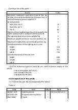
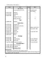
.6. The spanner 7 (Figure A.9) is intended for screwing out the ring 2
(Figure A.5) which fixes the cap of the illuminator 6 switch (Figure A.9), for
screwing out the screws 0 (Figure A.3) and 3 mechanisms for direction and
height adjustment and for screwing out the screws 7, 8 (Figure A.4) during
adjusting the aiming circle.
.6.2 The charge unit (Figure A.9) is intended for charging of the accumulators
NLTs-0.9-. When transported, is it put into the bag 8 (Figure A.9).
.6.3 The illuminator 6 is intended for mutual orientation of two observers,
as well as for illumination of the scales 7 and (Figure A.4) and of the needle
of the aiming circle 4.
.6.4 The bushing (Figure A.9) is intended for setting into the sighting
device 3 (Figure A.2) and into the illuminator 6 (Figure A.9) together with the
element ТHL-36 2.
.6.5 The napkin 0 is intended for cleaning external surface of the optical
elements.
.6.6 The soft cover 5 is intended for protection of the sighting device mounted
on the tripod from dust, precipitation and during breaks in operation.
Summary of Contents for 1PN91-2
Page 1: ...ARTICLE 1PN91 2 Service manual AL3 803 105 RE...
Page 2: ......
Page 37: ...37 2 1 3 1 cap 2 ring 3 cap Figure A 5 The illuminator...
Page 38: ...38 Figure A 6 The field of view of the sighting device...
Page 39: ...39 Figure A 7 The Landolt ring for checking illumination...
Page 40: ...40 Figure A 8 The chart for illumination defining Illumination lux distance m...
Page 43: ...43 1 91 2...


