www.nationalrailwaysupply.com
1-800-357-3572
6
38934B
Low Current Set Point Adjustment
The low current set point adjustment should be set to
a level that is below the charger output when
sourcing the minimum DC load of the system and
floating the fully charged battery set. The low current
set point adjustment is factory-set to approximately
400 mA (fully clockwise), which should work for most
applications. If the minimum DC load of the system
combined with the battery float current is above
approximately 500 mA, leaving the current limit
adjustment at the factory setting of 400 mA is
recommended. If an adjustment is required, it can
be adjusted between approximately 400 mA and 70
mA.
Adjustment Procedure
A small screwdriver (3/32 inch maximum blade
width) is required to change the low current set point
adjustment.
With AC power applied to the charger input and the
charger DC output connected to the load and fully
charged battery set, monitor the charger output
current until it stops decreasing and levels off at the
minimum system current. Ensure that the low
current set point adjustment is turned fully clockwise,
which will set the low current set point at
approximately 400 mA. If the LED is on and the
CLOSED relay contact is closed when the low
current set point adjustment is turned fully clockwise,
leave it in that position. If the LED is off and the
CLOSED relay contact is open when the low current
set point adjustment is turned fully clockwise, turn it
slowly counterclockwise until the LED turns on and
the CLOSED relay contact closes. Turn the low
current set point adjustment approximately 1/8 of a
turn counterclockwise from this switching point.
Remove AC power from the charger to verify that the
current monitor/alarm is functioning. The LED
should turn off and the CLOSED relay contact should
open.
Current Monitor/Alarm Specifications
RELAY CONTACT RATINGS:
1A at 30 Vdc
0.5A at 120 Vac
TERMINAL CONNECTIONS:
20 – 16 AWG wire, strip length of .312 - .359
inches (8 – 9 mm)
10. VOLTAGE MONITOR/ALARM
The ELC-24/30-CVM-D battery charger includes an
integrated voltage monitor/alarm that monitors the
DC voltage. Unless the optional VOLTAGE
MONITOR BATTERY SENSE input available on the
front of the charger is remotely wired to the terminals
of the battery, the DC voltage is monitored internally
at the charger output. If the DC voltage rises above
the HIGH VOLTAGE (HV) SET POINT setting, the
green BELOW HV SET POINT LED indicator is
turned off and the Form C, dry contact alarm relay is
actuated. If the DC voltage falls below the LOW
VOLTAGE (LV) SET POINT setting, the green
ABOVE LV SET POINT LED indicator is turned off
and the Form C, dry contact alarm relay is actuated.
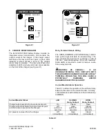
The voltage set point switches, LEDs, relay
terminals, and optional battery sense input are
accessible on the front of the charger (see Figure
10.1).
Figure 10.1


