
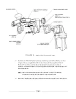

Page 10
Back Grind or “Undercut”
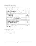
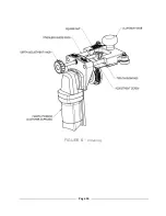
7.
The back grinding is done using the 2" cup wheel. Ensure adequate water flow is
provided by adjusting the valve. Lock the 2” cup wheel into the snail lock adapter and
back grind slightly more material than you'll be dressing off with the turbo pads.
Example – If 1 mm is going to be removed with the turbo pads, approximately 1.5 mm
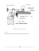
should be removed with the 2” cup wheel. One full turn of the Depth Adjustment Knob
(see figure 11 below) equals 1 mm. This material should be removed in ½ turn (0.5 mm)
increments until 1.5 mm is removed.
Be sure to stop the back grind short of the front profiled or polished edge to avoid a
large gap in the front edge. This back grind will allow the turbo pads to dress the upper
portion of the seam more efficiently and will also provide a rough surface on the lower
portion for the seaming adhesive to adhere to.
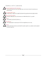
Caution
The SL3® Cup Wheel is made to be used with water. Adjust the water valve to ensure an adequate
water supply. DO NOT OVERHEAT the Cup Wheel by operating it dry. Max speed for the 2” Cup
Wheel is 10,000 RPM.
Dressing the Seam (Suggested Process)
8.
Start with either the SL3® 60 or 150 Grit Turbo Pad. Lock the desired turbo pad into the
snail lock adapter.
NOTE: Which grit to start with will depend on the size of chips in the edge, and how
much material is to be removed. Use the 60 grit to remove large chips and
excess material. Use the 150 grit for smaller chips and fragile material.
9.
Turn the adjustment knob counter clockwise to back the turbo pad off the stone so it’s
not touching the stone.
10.
Turn on the power and water. Adjust the water valve to ensure an adequate water
supply.
Caution
The SL3® Turbo Pads are made to be used with water. Adjust the water valve to ensure an adequate
water supply. DO NOT OVERHEAT the Turbo Pads by operating them dry. Max speed for the SL3®
Turbo Pads is 4,000 RPM.
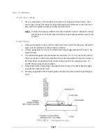
11.
Turn the adjustment knob clockwise until the turbo pad just touches the stone and
begin grinding the seam back and forth keeping the wheels in contact with the vertical
edge of the Glide Guide as shown in Figure 5 below.
!
!
Summary of Contents for 0010-1
Page 14: ...Page 14 FIGURE 6 Cleaning...


