Page 14 of 32
© Brüel & Kjær Vibro
● C104958.002 / V04
Technical alterations reserved!
EN
4.1.2
Displacement sensor for rear-side mounting
The sensor for rear-side mounting is assembled with the help of a sensor holder which preferably
includes an integrated bulkhead receptacle.
•
Fix the displacement sensor using a retainer that is appropriate for the type of installation.
We recommend using the holder AC-101/AC-3101.
4.2
Assembling the driver (oscillator/demodulator)
Assemble either:
•
with assembly adapter on a hat-rail
•
with assembly adapter via screw mounting on a firm surface
4.2.1
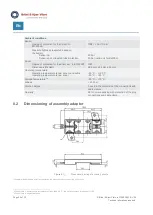
Mounting on hat-rail
*For mounting on a hat-rail, the mounting tabs for screw mounting can be separated at the predetermined breaking point.
1.
For screw mounting, break off both tabs and attach the driver with the assembly adapter by
sliding it into place (figure
).
2.
Affix the assembly adapter to a hat-rail (DIN EN 60715 TH35): Place rear part of the assembly
adapter (see figure above, item A) onto the guides of the hat-rail and press driver and adapter
downwards until the adapter clicks into place (figure
).
You need to secure the installed driver against misalignment with hat-rail end clamps. The hatrail end
clamps are included with our recommended protective driver housings AC-2126 for up to 3 drivers,
and AC-2127 for up to 6 drivers.

