© Brüel & Kjær Vibro
● C104958.002 / V04 ●
Page 19 of 32
Technical alterations reserved!
Brüel & Kjær Vibro
│
Instructions Sensor ds821 4 mm
Functional check
EN
UNRESTRICTED DOCUMENT
5
Functional check
Observe the safety information in chapter Safety!
5.1
Quick check
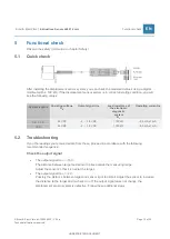
After installing the displacement sensor system, you can check the measured values using a digital
multimeter (Ri ≥ 100 kΩ). If the displacement sensor system is in correct operating condition, you will
see the following values:
System lengths Operating voltage
U
B
Output signal U
SIG
Load resistance of
the electronic
diagnostic
system
R
L
Operating current I
B
5 m; 10 m
-24 VDC
-2 ... -18 V DC
>100 kΩ
-8,9 mA ±1 mA
25; m
-24 VDC
-2 ... -18 V DC
>100 kΩ
-8,0 mA ±1 mA
5.2
Troubleshooting
If you the readings you receive deviate from these, proceed in accordance with the following
recommended sequence:
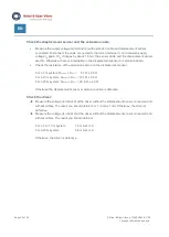
Check the output signal
•
The output signal U
SIG
< -18 V.
The distance between target and sensor tip lies outside the measuring range.
Adjust the sensor so that it is nearer the target.
•
The output signal U
SIG
> -2 V.
Possibly the distance between target and sensor tip is too small. Adjust the sensor to increase
the distance to the target and re-check U
SIG
. If the output signal does not change, the
displacement sensor system is defective. Follow these additional steps.

