© Brüel & Kjær Vibro
● C104958.002 / V04 ●
Page 21 of 32
Technical alterations reserved!
Brüel & Kjær Vibro
│
Instructions Sensor ds821 4 mm
Disassembly
EN
UNRESTRICTED DOCUMENT
6
Disassembly
Observe the safety information in chapter Safety! Follow reverse order for disassembly:
6.1
Disconnecting the connecting plugs
see “Connection via extension cable” on page 16
6.2
Driver disassembly
6.2.1
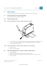
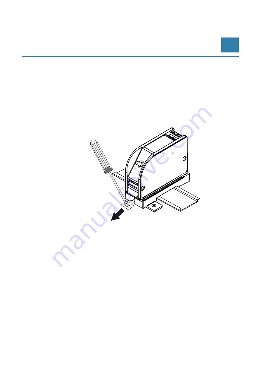
Disassembling driver with assembly adapter on hat-rail
1. Use a screwdriver to pull the tab forward and vertically lift off the adapter containing the driver.
2. To remove the assembly adapter, push the adapter's tappet (opposite of mounting tab)
downward and slide off the driver.
6.2.2
Disassembling driver with assembly adapter, screw-mounted
1. Remove screws.
2. Remove assembly adapter.
6.3
Replacing displacement sensor system components
1. Switch off voltage.
2. Replace the individual components with equivalent components.
3. Check that all parts of the displacement sensor system have been reconnected correctly.
4. Switch on voltage.

