background image


16


4.3.2 

Starting a sterilization cycle 

Press the key 

START/STOP

 to start the selected cycle. 


The programs


3

 and 

8


do not warrant the Class B sterilization; to start these types of cycle, hold down 

the key 

START


longer than 3 seconds


It is possible to program a delated starting of the cycle: hold on the 

START

 button longer than 8 sec-

onds, the display will  show 

HOUR  DELAY

,  using 

UP

  and 

DOWN

  select  the  time  delay  in  hours  than 

push 

START

; the unit will turn off indicating the residual time before to start; the chamber will cool.


It is 

possible to delete this action turning on the unit with 

POWER


For  unwrapped  solid  instruments  we  recommend  to  use  the  cycle 

3

  In  this  way  the  sterilization  time  will  be 

faster, and power consumption reduced

.


The door is locked and stays locked throughout the cycle duration. 

The sterilizer starts and runs the cycle phases automatically. The various steps of the cycle are microproces-
sor controlled and sequentially shown on the display; in this way the operator can monitor the progress of the 
sterilization phases and the times.  


Vacuum


phase

 (water entry in the chamber and pre-vacuum pulses) 

During  this  phase  the  microprocessor  enables  the  vacuum  pump  and  enters  a  water  dose  in  the 
chamber. The icon 

Vacuum 

is flashing. This phase will be repeated more times and should require 10 

to 20 minutes depending on the chamber conditions and load type to be processed.  This phase may 
be slightly noisy. 

Sterilize


Reached the preset parameter values, icon 

Vacuum 

turns off and Led 

Sterilize 

turns on. The display 

time


starts the countdown marking the time remaining to the end of the sterilization phase. 

The sterilization phase is followed by the decompression phase,  the  pressure  decreases  to 0. Again, 
the display shows the countdown of the decompression phase. Based on our experiences, the decom-
pression time has been slightly extended in order to minimize the thermal shock consequent to the sta-
tus change of the steam. 


Drying  

Over the decompression phase, 

Sterilize  icon 

starts to flash to signal the completion of the steriliza-

tion process. At the same time 

Dry 

turns on, signalling the start of the drying phase. Throughout this 

phase, the chamber heaters keep the chamber warm according to a  microprocessor-controlled  logic, 
the  vacuum  pump  comes  again  into  operation  to  eliminate  the  residual  moisture.  The  display  shows 
the countdown of this phase. Follows the forced ventilation phase through the bacterial filter 

– the dis-

play shows also the countdown of this phase. 


End of the cycle 

As soon as the drying is over, 

Dry 

turns off and 

Ready 

and

 Sterilize 

turn on. A 10-second alert signal 

is  generated  to  draw  the  attention  by  the  operator.  The  chamber  heaters  are  set  at  reduced  power 
(pre-heating, only if 

ECO MODE

 is not selected) until the door is open. The TIME display shows the to-

tal  time  of  the  cycle, the  displays  TEMP.  and  PRESS  show  respectively  the  current  temperature  and 
pressure of the chamber. 


At the end of cycle 3 or 8 only the Led 

READY

 will light and not

  STERILIZE

 to signal that 

the cycle selected by the operator does not warrant a Class B sterilization

;

 the display will 

show the cycle counter.


Summary of Contents for iClave Plus

Page 1: ...Rev 1 Date June 2015 plus Water Steam Sterilizer Class B OPERATION MANUAL...

Page 2: ...all the agent Thanks for the confidence given All rights reserved No portion of this publication can be printed transmitted rewritten stored in a data recovery system translated in any foreign or comp...

Page 3: ...1 Available sterilization cycles 15 4 3 2 Starting a sterilization cycle 16 4 4 STOPPING THE CYCLE 17 4 5 TOPPING UP AND DRAINING THE WASTE WATER TANK 18 4 5 1 Topping up the main tank 18 4 5 2 Drain...

Page 4: ...t damages or missing parts see delivery note IN CASE OF DAMAGES OR MISSING PARTS PLEASE IMMEDIATELY INFORM AND IN DETAIL THE FORWARDER NSK AND ITS AREA AGENT 1 2 CONFORMITY TO EUROPEAN DIRECTIVES The...

Page 5: ...3 1 3 PACKAGE DIMENSIONS AND WEIGHT Total weight 58 Kg Store the package for possible future shipment 1 4 UNPACKAGING...

Page 6: ...1 OVERALL DIMENSIONS 2 2 USABLE SPACE IN THE CHAMBER Diameter 240 mm Depth 384 mm Capacity 17 5 l Useful dimensions per tray 315 x 214 mm x 2 315 x 168 mm x 2 Useful tray volume 10 l Net weight 47 Kg...

Page 7: ...heard pull it gently you have to feel that the cap is free to move The valve can not be adjusted or serviced for safety reasons Follow the maintenance program described in the ap pendix SERVICE BOOK...

Page 8: ...ent sterilization cycle has not been successfully completed The water waste contained in the recovery tank is to be regarded as biologically contaminating therefore when this tank is emptied suitable...

Page 9: ...fresh water tank drain Quick connector for waste water tank drain Water inlet filter Temperature sensor Air line filter Safety valve connection Safety valve Automatic draining of used water tank opti...

Page 10: ...y may be replaced only by au thorized service Varta CR2032 Sterilization time from 3 to 90 depending on the selected cycle Transmitted heat in environment 0 22 J h at 23 C Drying time from 6 to 14 dep...

Page 11: ...ater easier during the drain phase WARNING do not place the unit on surfaces which could cause fire or fume if hot items fall from the equipment 3 For the correct operation it is mandatory to leave a...

Page 12: ...he trays from the chamber and close the door When the unit is off the door is blocked if the block per sists turn off and then on again the unit 4 Hold on the key UP and push the key Power the display...

Page 13: ...the factory test the equipment is set at a default value of 100m and can be left unchanged for real alti tude values between 0 and 200m since a 100m error does not affect the equipment operation To b...

Page 14: ...ake another cycle Phase in progress signalling Led turned on or flashing during the phases of the cycle LCD displays Visualize from the top the value of the parameters Time when the unit is OFF Temper...

Page 15: ...e numbers to the right indicate the value of the temperature in the chamber expressed in Celsius degrees Cycle class indicators B or S Temperature cycle indicators 121 C for cycles 2 and 7 134 C for c...

Page 16: ...a fata backup The size of the data is limited to few Kbyte so a small capacity is needed a big amount of data stored in the USB stick decreases the speed of access so it is suggested to delete the fil...

Page 17: ...mperature reading on the display is inaccurate because no steam being there 3 Arrange the material to be sterilized on the trays load the chamber and close the door 4 Check the indication of the water...

Page 18: ...values icon Vacuum turns off and Led Sterilize turns on The display time starts the countdown marking the time remaining to the end of the sterilization phase The sterilization phase is followed by th...

Page 19: ...ready warm or press key Power to put the unit in stand by status OFF on the display If the door is not opened or a key pressed within 30 minutes the unit switches to stand by OFF automatically WARNING...

Page 20: ...n again only af ter one cycle or if the unit is switched off then the icon will blink again with the empty symbol when there is not enough water to run another cycle the current cycle will be anyway c...

Page 21: ...value than push START the display shows SPECIAL TIME using UP and DOWN select the value than push START the display shows VACUUM SPECIAL using UP and DOWN select the value than push START the display...

Page 22: ...umber of prints needed with UP and DOWN the print starts opening the door LANGUAGE selects the language of the display messages and cycles report ALTITUDE adjust the elevation above the see level of t...

Page 23: ...avoid excessive heating To close the door switch on the unit again 1 Put a cleaning tab in the chamber and close the door THE CHAMBER MUST BE EMPTY 2 Select the cycle C CLEANING 3 Push START this cyc...

Page 24: ...s is EN13060 ch 10 6 for the B type cycles and ch 10 5 for the S type For any explanations or information contact your authorized reseller or directly NSK 6 4 1 Porous load test B D The test can be pe...

Page 25: ...ture and with the main tank full At the end of the auto test the display will show the message H2O good or H2O hard if the meas ured conductivity value is respectively lower or higher than 15 S ATTENT...

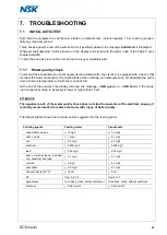
Page 26: ...the mes sage appears before starting a cycle Top up the main tank FULL H2O The waste water tank is full the message ap pears before starting a cycle Drain the waste water tank MANUAL STOP Cycle manua...

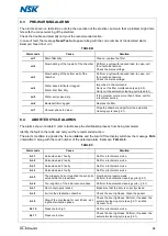
Page 27: ...1 8 4 ABORTED CYCLE ALARMS The alarms shown on table C refer to faults keep the sterilization process from being completed Identify the fault on the table and carry out the recommended action The alar...

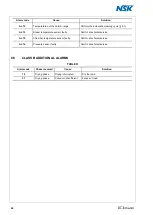
Page 28: ...aulty Call for a technical service AL 15 Chamber temperature sensor faulty Call for a technical service AL 16 Pressure sensor faulty Call for a technical service 8 5 CLASS B ADDITIONAL ALARMS TABLE D...

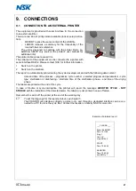
Page 29: ...le development and with the following data content date and time of the process progressive cycle number selected program and parameters cycle type sterilization or disinfecting start end time of the...

Page 30: ...e technician is able to detect any significant data of the machine and to per form more quickly and cheaply both troubleshooting and repairing Moreover the system allows the connection via external mo...

Page 31: ...Standard periodic checks Pos Check Activity Ordinary maintenance Special maintenance 1 Door adjustment 1 Year 1 500 cycles Gasket replacement 1 Year 1 500 cycles Disk door clearance check 1 Year 1 500...

Page 32: ...es Aborted cycles Alarm code Technician name Door adjustment Filter Calibration Cond cleaning Pump Tank cleaning Notes Sterilizer OK YES NO Date No of cycle Cleaning cycles Aborted cycles Alarm code T...

Page 33: ...es Aborted cycles Alarm code Technician name Door adjustment Filter Calibration Cond cleaning Pump Tank cleaning Notes Sterilizer OK YES NO Date No of cycle Cleaning cycles Aborted cycles Alarm code T...

Page 34: ...les Aborted cycles Alarm code Technician name Door adjustment Filter Calibration Cond cleaning Pump Tank cleaning Notes Sterilizer OK YES NO Date No of cycle Cleaning cycles Aborted cycles Alarm code...

Page 35: ......

Page 36: ...ht to make any altera tions which may be due to technical im provements Sous r serve de modifications dues au progr s tech nique Reservados los derechos de modificati n en virtud del progreso t cnico...

Reviews:

Related manuals for iClave Plus