— 6-4 —
6.4. Driver Unit Mounting
l
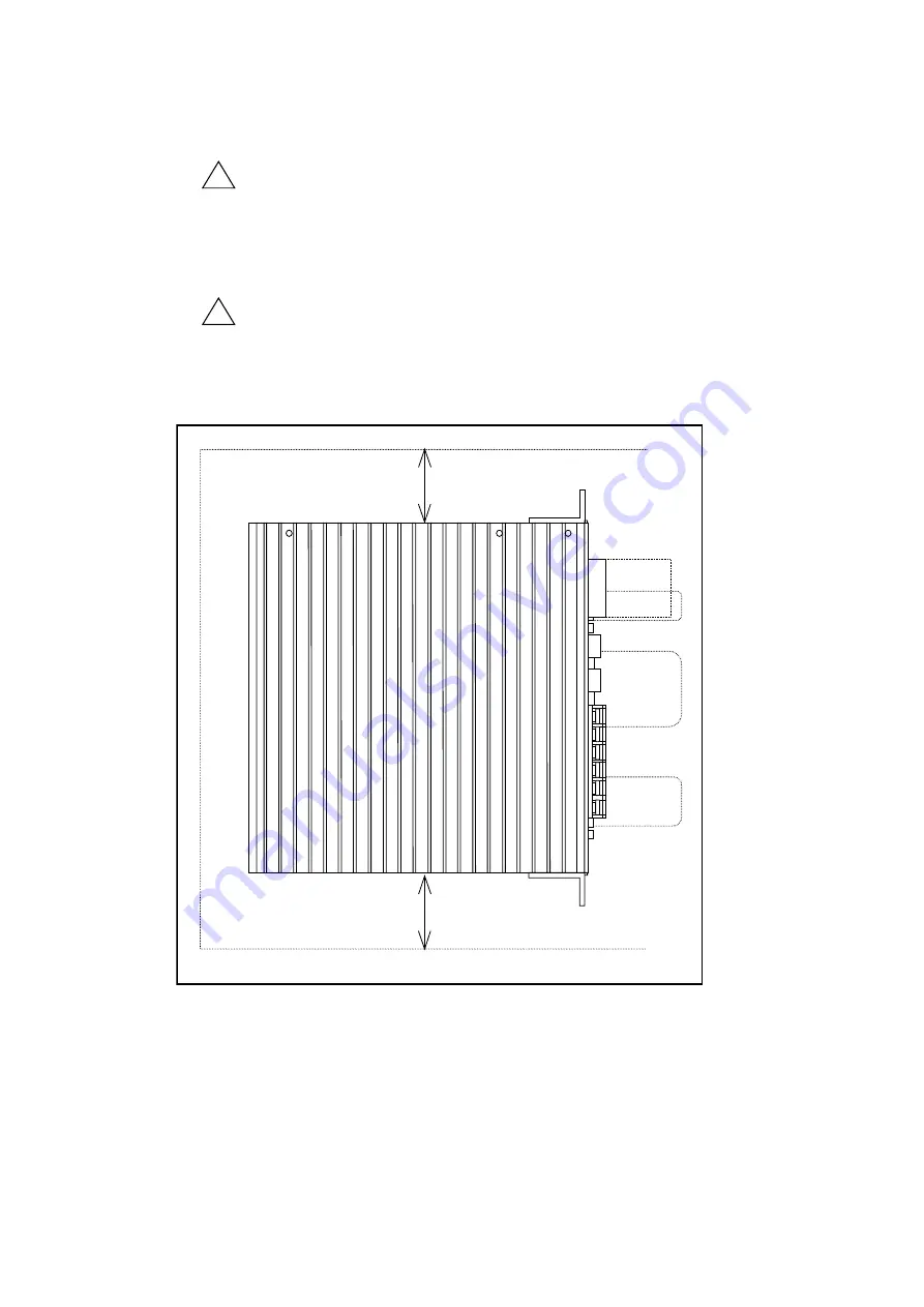
The ESA13 Driver Unit may be mounted by the holes in brackets.
!
Caution : For proper air circulation, clearance is required above, below, and at the
back of the unit (see Figure 6-7).
l
When the Driver Unit is installed in the control panel, keep the panel internal temperature within
the range from 0°C to 50°C. If the heat sink overheat alarm (see “14. Alarms”) arises frequently,
cool the heat sink using a fan, etc.
!
Caution : When installing two or more Driver Units for multi-axis combinations,
give a space of about 10 cm between adjacent Driver Units.
l
ESA13 Driver Unit has brackets for easy fixing to the control box or enclosure.
Figure 6-2
10cm or more
10cm or more
Reference: Maximum power dissipation of ESA13 Driver Unit is 100W.
l
The area where the Driver Unit is mounted must be free of water, corrosive gas, dirt, dust and
any other contamination.
Artisan Technology Group - Quality Instrumentation ... Guaranteed | (888) 88-SOURCE | www.artisantg.com


