3
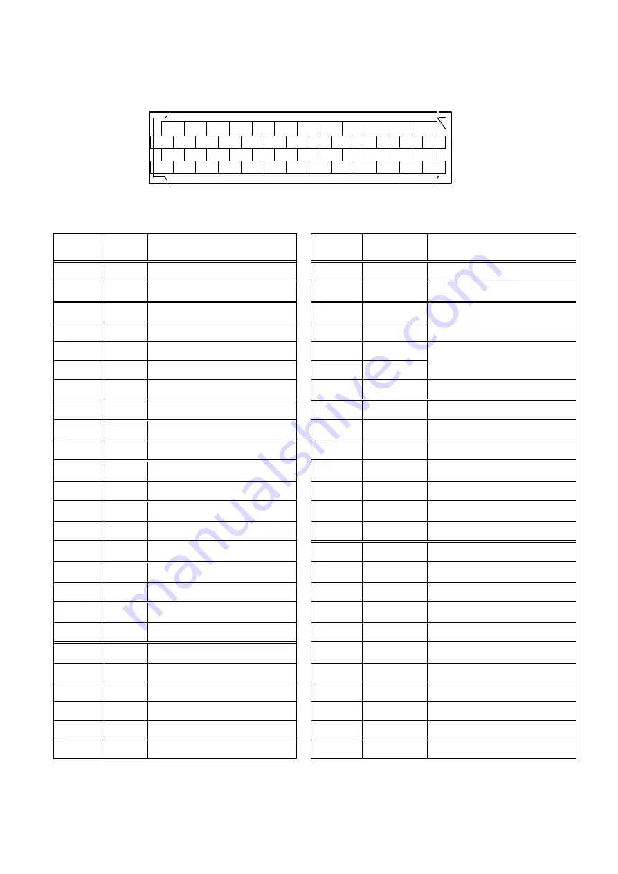
CN1 signal and Pin number.
■
CN1
10150-3000PE (Soldering side view)
Signal name and its function. (shipping set)
Terminal
number
Signal
name
Description
Terminal
number
Signal
name
Description
1
-
Do not connect
30
MON1
Analog monitor output
2
-
Do not connect
31
SG
Common for pin 30
3
A0
A phase pulse output
13
CONT7
Position command pulse
disabled function/shutdown at
zero velocity function
4
A0
/A phase pulse output
14
CONT7
5
BO
B phase pulse output
15
CONT8
Alarm reset function
6
BO
/B phase pulse output
16
CONT8
7
ZO
Z phase pulse output
38
SG
Common for pins 13 to 16
8
ZO
/Z phase pulse output
32
CONT6
CW over travel function
9
PS
Resolver signal output
33
CONT5
CCW over travel function
10
PS
/Resolver signal output
34
CONT4
Deviation clear function
11
ZOP
Z phase pulse output
35
CONT3
Magnetic pole position estimation input
12
SG
Common for pins 3 to 11
36
CONT2
Emergency stop function
17
-
Do not connect
37
CONT1
Servo-ON function
18
-
Do not connect
50
CONT-COM
General input power supply
19
-
Do not connect
39
OUT1
In-Position window
20
-
Do not connect
40
OUT2
Magnetic pole position estimation ready
21
-
Do not connect
41
OUT3
Operation setup completion
22
T-COMP
Torque compensation input
42
OUT4
Magnetic pole position estimation end
23
SG
Common for pin 22
43
OUT5
Alarm code bit 5
26
F-PC
CW command pulse input
44
OUT6
Alarm code bit 6
27
F-PC
CW command pulse input
45
OUT7
Alarm code bit 7
28
R-PC
CCW command pulse input
46
OUT8
Alarm status
29
R-PC
CCW command pulse input
49
OUT-PWR
Power source for general output
47
SG
Common for pins 26 and 27
24
OUT-COM
General output Common
48
SG
Common for pins 28 and 29
25
OUT-COM
General output Common
24
22
20
18
16
14
12
10
8
6
4
2
25
23
21
19
17
15
13
11
9
7
5
3
1
49
47
45
43
41
39
37
35
33
31
29
27
50
48
46
44
42
40
38
36
34
32
30
28
26


