NTi
®
Rudolf Ille Nachrichtentechnik • P.O.Box 1703 • D-79507 Loerrach
Tel. +49 7621 / 14756 • Fax +49 7621 / 18840 • www.nti-online.de
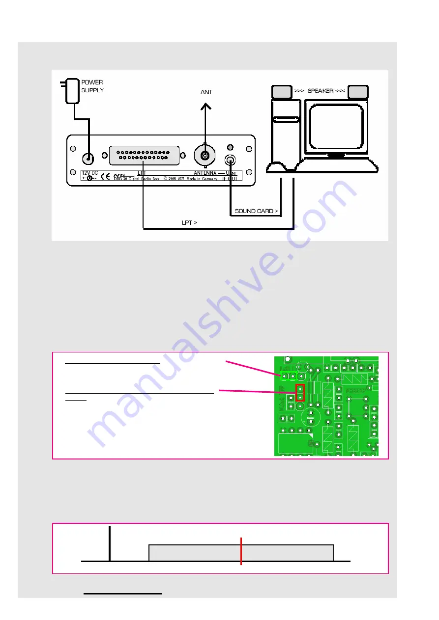
Connections
Please note: Connecting cables and power supply are not included !
• PC:
Parallel Interface LPT (25pin D-SUB male/female cable)
&
Sound Card / LINE input (2x 3.5mm stereo phone
plug)
• Antenna:
BNC (2x male)
Optional: Active antenna with power supplied via the antenna cable . For more details refer below.
•Power supply:
Plug-power supply 12-15V DC min. 200mA (2.1mm); positive inner, negative outer
Please note: The signal quality of the DiRaBox corresponds to the quality of the conncted power supply (output voltage ripple).
Simple and unstabilized plug-power supplies are insufficient.
We recommend therefore stabilized power supplies or shielded
switching power supplies.
• Audio output:
Sound is provided by the soundcard via connected earphones or by loudspeaker.
Optional Internal Jumper Settings
Spectral Display
When running SDR software with a spectral display please note:
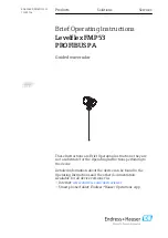
• The DRB 30 second IF value is 10KHz, therefore every signal tuned by the DiRaBox Control Panel software is
displayed at the 10KHz marking position.
• Due to the 15KHz IF bandwidth the passband range is +/- 7.5KHz around the 10KHz center frequency.
0 10KHz
Display Frequency
IF bandwidth
(+/- 7.5KHz)
IF output stereo phone jack
Left + Right(L+R) >>> Default
or only left channel (L)
Remote voltage supplied via antenna socket
(BNC) for an optional active antenna
OFF >>> Default
When set to ON: Additional remote supply
voltage 9V via 470 Ohms serial resistor
(short circuit limiter.
The red rear panel LED "U ANT" lights up
simultaniously.
If the antenna cable is short-circuited the
red LED will fade !


