background image

In some cases you will need to know what IMEI number is associated with your E-AVDS-GSM.    Follow these steps to locate and 
record the number.  
 
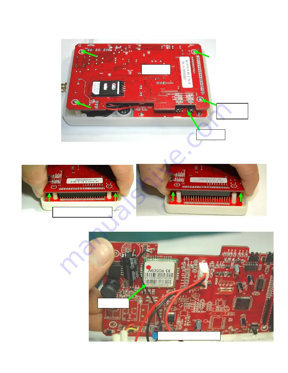
1. While the case is still open (after installing the Mini SIM card),   remove the 4 screws that secure the rear circuit board to the front 
circuit board.  


2. With the screws removed, carefully pull the rear circuit board off of the front circuit board.   Lift the circuit board straight up to 
separate them.  


3. Gently lay back the circuit board and locate the IMEI number on the chip on the backside of the rear circuit board.  
 
 
4.  Record the IMEI number  
and carefully re-assemble the 
circuit boards.  


Front PCB 

Rear PCB 

Remove 
Screws (4 ) 

Separate the circuit boards 

IMEI Number 

Backside of rear circuit board 

Summary of Contents for E-AVDS-GSM

Page 1: ...atically activates the phone or in this case the E AVDS GSM into which it is inserted SIM cards are available in three standard sizes The first is the size of a credit card 85 60 mm 53 98 mm x 0 76 mm...

Page 2: ...e down on a clean surface The Mini SIM card holder will be facing you 2 Slide the top of the card holder to the right A gap will appear between the top and bottom of the cardholder 3 Flip the top fram...

Page 3: ...sert the card all the way in until it stops 5 Fold the top frame back on top of the bottom The card should set into the same shaped recess in the bottom 6 Slide the top frame to the left to lock the f...

Page 4: ...this configuration a relay closure will trigger an alert state activating the dialer To set the normal relay state to Normally Closed apply the J2 and J1 jumpers to the center and left pins In this c...

Page 5: ...the front circuit board 2 With the screws removed carefully pull the rear circuit board off of the front circuit board Lift the circuit board straight up to separate them 3 Gently lay back the circui...

Page 6: ...ETHODS Connect the cable from the E AVDS GSM to the E xD according to one of the following diagrams Note The attached cable is 27 long but can be extended up to 250 feet with any 3 conductor 22AWG min...

Page 7: ...7...

Page 8: ...E1 through E8 indicators will illuminate while setting the password 5 GSM indicator a LED OFF GSM module power is OFF or doesn t work b 600ms milliseconds ON and 600ms OFF SIM card has not been insert...

Page 9: ...number followed by two beeps To clear and refresh the service provider phone number press 0 and then ENTER The LED will display A to indicate a correct input It will then automatically search for and...

Page 10: ...wer cycling the dialer allow it to restore connection with the service provider and try this procedure again If no SMS message is programmed the default SMS message sent will be DA 911 ALARM 6 Test Pr...

Page 11: ...message was sent successfully It will not follow the programmed number of retries 9 Save and Review Password The dialer supports a 4 digit private password Default password is 0911 To change the defa...

Page 12: ...word is accepted the password will then be displayed the alarm state will be discontinued and two beeps will be heard The E AVDS GSM will return to normal operating mode If the user enters the wrong c...

Page 13: ...one number and alarm receiving method Display alarm means 1 or 2 A then phone number followed by two beeps 4 Ex Test the recipient phone number and alarm receiving method Display A if successful Displ...

Page 14: ...ering duration 0 5 seconds or 3 seconds default is 0 5s Voice recording 20 seconds maximum Phone numbers Up to 8 contact numbers Private password protection 4 digit private password programmable Defau...

Reviews: