background image

NTI UNIMUX SERIES USB KVM SWITCH 


6


INSTALLATION 


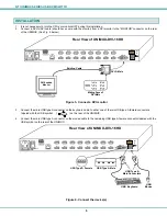
1.  It is not necessary to turn the CPUs or monitors OFF during this installation.   
2.


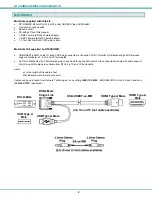
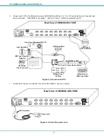
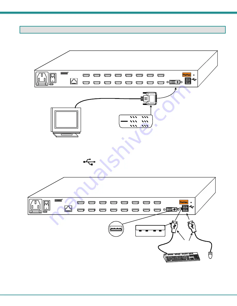
Connect a DVI-to-DVI cable (should have come with the monitor) from a DVI monitor to the “MONTOR” connector on the rear 
of the UNIMUX  (See Fig. 3 below.) 


Figure 3- Connect a DVI monitor


3.


Connect the male USB type A connector on the keyboard cable to either one of the two USB type A female connectors  

        labeled with the USB symbol     (                  ) on the rear of the UNIMUX.   
 
4.


Connect the male USB type A connector on the mouse cable to the remaining USB type A female connector labeled with the 
USB symbol on the rear of the UNIMUX.  


Figure 4- Connect the device(s)


DVI Enabled 

Monitor

Mating Face of

DVI Male

Rear View of UNIMUX-DVI-16HD

CPU 1

CPU 2

CPU 3

CPU 4

CPU 5

CPU 6

CPU 7

CPU 8

CPU 9

CPU 10

CPU 11

CPU 12

CPU 13

CPU 14

CPU 15

CPU 16

RS232

250V,2A

MONITOR

NTI

Tel:330-562-7070
Fax:330-562-1999

1275 Danner Dr
Aurora, OH 44202

  www.n etworktech inc.com

R

 DVI-D-Male


Existing Cable

DDC

1

8

ON

RS232

USB  Keyboard 

 USB 

Mouse

USB Type A 

Male Connectors 

 USB Type A Male     

 USB Type A Female     

Rear View of UNIMUX-DVI-16HD

CPU 1

CPU 2

CPU 3

CPU 4

CPU 5

CPU 6

CPU 7

CPU 8

CPU 9

CPU 10

CPU 11

CPU 12

CPU 13

CPU 14

CPU 15

CPU 16

RS232

250V,2A

MONITOR

NTI

Tel:330-562-7070
Fax:330-562-1999

1275 Danner Dr
Au rora, OH 44202

  www.networktechinc.com

R

DDC

1

8

ON

RS232

Summary of Contents for unimux-dvi(a)-xhd

Page 1: ...MAN005 Rev Date 12 13 2013 UNIMUX DVI A xHD USB DVI KVM Switch Installation and Operation Manual UNIMUXTM Series ...

Page 2: ...r Drive Aurora Ohio 44202 CHANGES The material in this guide is for information only and is subject to change without notice Network Technologies Inc reserves the right to make changes in the product design without reservation and without notification to its users CE Statement We Network Technologies Inc declare under our sole responsibility that the UNIMUX DVI A 4 8 16 32 is in conformity with Eu...

Page 3: ...erface Test Program 16 Main Options 16 KEYBOARD FEATURES 18 Keyboard To Computer Translation 18 Translation Capabilities 18 Translation Tables 18 International Sun Keyboards 19 DDC 20 AUDIO SUPPORT 20 TROUBLESHOOTING 21 INDEX 22 WARRANTY INFORMATION 22 TABLE OF FIGURES Figure 1 Secure rackmount ears to switch 5 Figure 2 Secure switch to a rack 5 Figure 3 Connect a DVI monitor 6 Figure 4 Connect th...

Page 4: ...iii Figure 16 Rear View of UNIMUX DVIA 8HD 20 ...

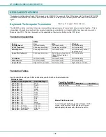
Page 5: ...Input Devices Supported USB keyboard with Windows layout USB keyboard with SUN layout USB keyboard with MAC layout USB Mouse up to 3 buttons USB IntelliMouse scrollwheel USB Hub Mouse Trak trackball Logitech Kensington and Microsoft Wheelmouse or Trackball on Mac CPUs with special drivers Logitech Cordless Elite Duo keyboard and mouse Logitech wireless S510 EX110 diNovo LX710 MX5000 Crystal Vision...

Page 6: ...nitor USB keyboard and USB mouse support available in 3 6 10 and 15 foot lengths An SA xx MM cable with 3 5mm stereo plug on each end for each audio source to be connected models with audio support only SA xx MM cables are available from NTI in 3 6 10 and 15 foot lengths where xx is the length of the cable in feet MM indicates male to male connector Cables can be purchased from Network Technologie...

Page 7: ...ces connect to CPU Enclosure that contains the operating system and processor i e Sun with SPARCstation5 Windows 95 with Pentium II Input Device Keyboard or Mouse System One or more CPUs connected to one or more switches controlled by one or more input devices Front View of UNIMUX DVI 8HD USB Keyboard USB Mouse DVI Enabled Monitor USB CPU USB CPU USB DHEXT xx MM Typical Application Existing cables...

Page 8: ...nnector for connection of the cable from the CPU s 8 MONITOR female DVI connector for connecting DVI cable from user monitor 9 RS232 DIP switches for configuring switch address when RS232 is used 10 USB USB type A female connector for connection of user USB keyboard and mouse 11 DDC for refreshing the DDC information between the monitor and CPU 7 Rear View of UNIMUX DVI 16HD 1 3 Front View of UNIM...

Page 9: ...ded holes in the sides of the NTI switch Tighten the screws securely Figure 1 Secure rackmount ears to switch 2 Install 4 cage nuts not supplied to the rack in locations that line up with the holes in the mounting ear on the NTI switch 3 Secure the NTI switch to the rack using four rack screws 10 32 12 24 M6 etc not supplied Each screw should be of sufficient length to go completely through the NT...

Page 10: ...nnector labeled with the USB symbol on the rear of the UNIMUX Figure 4 Connect the device s DVI Enabled Monitor Mating Face of DVI Male Rear View of UNIMUX DVI 16HD CPU 1 CPU 2 CPU 3 CPU 4 CPU 5 CPU 6 CPU 7 CPU 8 CPU 9 CPU 10 CPU 11 CPU 12 CPU 13 CPU 14 CPU 15 CPU 16 RS232 250V 2A MONITOR NTI Tel 330 562 7070 Fax 330 562 1999 1275 Danner Dr Aurora OH 44202 www networktechinc com R DVI D Male Exist...

Page 11: ...HDMI Type A Video Connector Mating Face of DVI Male Mating Face of HDMI Type A Male Rear View of UNIMUX DVI 16HD CPU 1 CPU 2 CPU 3 CPU 4 CPU 5 CPU 6 CPU 7 CPU 8 CPU 9 CPU 10 CPU 11 CPU 12 CPU 13 CPU 14 CPU 15 CPU 16 RS232 250V 2A MONITOR NTI Tel 330 562 7070 Fax 330 562 1999 1275 Danner Dr Aurora OH 44202 www networktechinc com R USB DHEXT xx MM 3 6 10 and 15 foot cables available DDC 1 8 ON RS232...

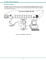
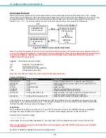
Page 12: ...inal Follow the instruction under RS232 Control on page 13 for configuration and use of the RS232 control feature Figure 7 Connect RS232 control terminal VGA Multi Scan Monitor Control Terminal RJ45 to DB9 Adapter supplied CAT5 Patch Cable supplied RJ45 to DB25 Adapter supplied or Rear View of UNIMUX DVI 16HD CPU 1 CPU 2 CPU 3 CPU 4 CPU 5 CPU 6 CPU 7 CPU 8 CPU 9 CPU 10 CPU 11 CPU 12 CPU 13 CPU 14 ...

Page 13: ...ice or hub cables can be connected to the UNIMUX at the USB Type A female ports See Features and Functions on page 3 item 11 A USB hub single or multi port can be used provided only USB input devices are plugged into it Only a USB Windows or SUN keyboard or USB mouse may be connected to the USB port on a USB MAC keyboard A maximum of 8 input devices may be connected to the UNIMUX either directly o...

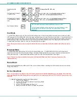
Page 14: ...y the CPU to which the user is connected through the UNIMUX Keyboard Control Keyboard control of the UNIMUX can be achieved using Command Mode below The keyboard can be used to control all functions of the UNIMUX as an alternative to using the front panel on the UNIMUX By pressing Ctrl accent tilde key the user can enter Command Mode Once in Command Mode typing a series of commands will cause the ...

Page 15: ...ain ON while in Broadcast Mode Broadcast Mode enables the user to type characters to all powered ON CPUs simultaneously To deactivate Broadcast Mode press B from the Command Mode menu again Note The user must type somewhat slowly when in Broadcast Mode less than 20 wpm and cannot use the Backspace key Normal Mode When all of the UNIMUX mode LEDs are OFF the user is in Normal Mode controlling the C...

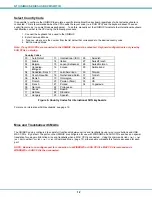
Page 16: ...Belgian 15 Japan Katakana 28 Swiss German 03 Canadian Bilingual 16 Korean 29 Switzerland 04 Canadian French 17 Latin American 30 Taiwan 05 Czech Republic 18 Netherlands Dutch 31 Turkish 06 Danish 19 Norwegian 32 UK 07 Finnish 20 Persian Farsi 33 US 08 French 21 Poland 34 Yugoslavia 09 German 22 Portuguese 10 Greek 23 Russia 11 Hebrew 24 Slovakia 12 Hungary 25 Spanish Figure 9 Country Codes for int...

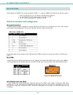
Page 17: ...it data RXD at host 7 No connection 8 No connection A 5 foot patch cable and two adapters RJ45 to DB9 and RJ45 to DB25 have been provided for connection to most CPUs see page 8 Baud Rate The baud rate can be changed by powering down the unit changing the 8 position RS232 DIP switch on the rear of the UNIMUX and then powering back up This table shows how to set the baud rate Fig 10 shows switches i...

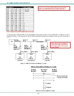
Page 18: ... serial adapter provided with the RS232 option and the CPU as shown in Fig 11 Figure 11 RS232 connection with Matrix Y 1 cable Figure 12 Pinout of Matrix Y 1 cable Unit 1 Source 2 3 3 3 5 5 5 2 2 7 8 1 4 6 Jumper Jumpers Not connected to source connector Unit 2 9D Female 9D Male 9D Male Wiring Schematic of Matrix Y 1 cable Note The loop back RS232 DIP switch RS232 DIP switch 1 should be ON for eac...

Page 19: ...P CR IP CR Read Connection For Output User Port to Input CPU Port RS SW CR Internal Reset RU SW CR IP OP CR Read Unit Size SS SW 00 CR Disable Autostatus feature see below SS SW 01 CR Enable Autostatus feature see below GO SW OP CR go SW OP IP CR Read connection of a Output User Port to Input CPU Port different response format than RO command GM SW 00 CR go OP IP all ports CR Read connection matri...

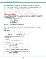
Page 20: ...e Test Program This software allows a user to test the functions of an NTI server switch matrix switch or Multi user Multi platform Single user switch RS232 interface The SerTest program is automatically loaded when installing the NTI Switch Control Program as described above The SerTest program located in the NTI program group generates a main menu with the 4 selections described below Main Optio...

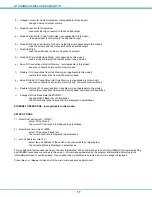
Page 21: ...ons into switch memory bank command for all switches h Restore All Units I O Connections from Units Memory not applicable to this model restore the connections from switch memory bank command for all switches i Change All Units Baud Rate 9600 COM1 change RS232 Baud rate of all switches the current baud rate and serial port are displayed in parentheses ETHERNET OPERATIONS not applicable to this mod...

Page 22: ...onality Full functionality except Application Key Apple Pro Keyboard Extra keys emulation Extra Keys not supported Eject Mute Volume Volume Full functionality Sun Mouse Full functionality Full functionality Full functionality Wheel Mouse Full functionality Full functionality Full functionality Apple Mouse Right button emulation Full functionality Right button emulation Translation Tables Use the c...

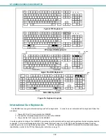
Page 23: ...manually set the UNIMUX to indicate the international keyboard identification number to the CPU by following the instruction on page 12 Enter Enter Ctrl Shift Shift Caps Lock Tab Esc Ctrl Alt Backspace Num Lock Windows USB Keyboard Alt Enter Enter Ctrl Shift Shift Caps Lock Tab Esc Ctrl Alt Backspace Num Lock Typical 101 Keyboard Alt F1 F2 F3 F4 F5 F6 F7 F8 F9 F10 F11 F12 Scroll Lock Pause Break P...

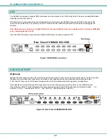
Page 24: ...pport include 3 5mm stereo jacks for connection to audio sources and an output device Audio from either the same sources as the video keyboard and mouse or from separate sources any standard line level audio source 1 23Vrms 3 47Vp p max will be heard through devices such as self powered stereo speakers or headphones Audio signals are switched along with the keyboard mouse and video signals using t...

Page 25: ... re booted in order to sense the monitor connection Make sure monitor is configured for digital DVI video not analog DVI See your monitor instructions for how to do this Press the DDC button on the back of the unit PROBLEM No Mouse Movement SOLUTION Check cable connections of mouse Verify that mouse driver was loaded PROBLEM Unit is not displaying full 1920x1200 1920x1024 works OK SOLUTION If sour...

Page 26: ... MAC mice and trackballs 12 materials supplied 2 Matrix Y 1 cable 14 power up sequence 9 Rackmounting 5 RS232 commands 15 RS232 Control 13 RS232 pinout 13 Scan mode 11 SerTest 16 Sun sleep mode 11 Switch Control Program 16 WARRANTY INFORMATION The warranty period on this product parts and labor is two 2 years from the date of purchase Please contact Network Technologies Inc at 800 742 8324 800 RGB...

Reviews: