NTI UNIMUX MULTI-USER KVM SWITCH
12
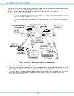
1. Position the ST-C5USBV-R-300 such that the CAT5 cable, the monitor cable, the keyboard and mouse, and the AC adapter
power connector can each reach the ST-C5USBV-R-300 comfortably.
2. Connect the monitor cable to the 15HD female VIDEO port on the ST-C5USBV-R-300. (See Figure 10)
3. Connect the devices to the ST-C5USBV-R-300.
a.
Connect the USB keyboard cable to one of the USB Type A female ports labeled "USB DEVICES" on the back
of the ST-C5USBV-R-300. (Either one will work.)
b.
Connect the USB mouse cable to the remaining USB Type A female port on the back of the ST-C5USBV-R-
300.
Figure 10- Connect monitor and devices to ST-C5USBV-R-300
4. Plug the power cord from the monitor into a power outlet.
5. Connect the AC adapter power connector to the 9VDC port on the Remote Unit and plug it into a power outlet. The “Power”
LED (Green) on the CAT5 connector of the Remote Unit should illuminate, indicating that a proper power connection has
been made.
6. Turn ON the monitor. The monitor will display an image coming from the CPU that User 3 is connected to via the UNIMUX
switch. The yellow communication LED on the Remote Unit (see Figure 10) should blink indicating there is proper
communication with the UNIMUX.
VGA
Multi-Scan
Monitor
15HD Female
Video Connector
CAT5 Cable to
"USER 3" on
UNIMUX-4X8-UHDUC5
Green Power LED
Yellow Communication LED
(Front View)
NTI
R
Network Technologies Inc
XTENDEX
USB
-
+
XTEN
DEX
USB
NTI
R
Netw
ork
T e
c h
nol
og
ie
s In
c
(Rear View)
-
+
USB Keyboard
USB
Mouse
USB Type A
male connectors
USB Type A male
ST-C5USBV-R-300 Remote Unit
USB Type A Female
15HD male
Video Connector


