No. PMPH022E-c
- 1 -
INSTRUCTION
MANUAL
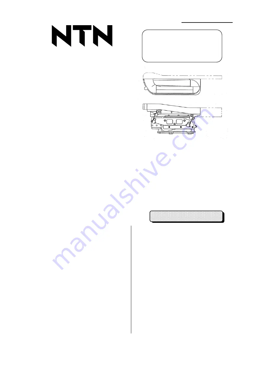
NTN Mono-Drive
2-Way Feeder
Type MD10
・
B(C)
/
MD20
・
B(C)
/
MD30
・
B(C)
Introduction
Thank you for your purchase of the NTN mono-drive 2-way feeder.
For correct operation of the NTN mono-drive 2-way feeder, read this Instruction Manual carefully before
use, and ensure execution of safe work through correct operation.
Be sure to deliver this Instruction Manual to the end user. The end user is further requested to store the
Instruction Manual carefully in a ready-to-take out place to facilitate ready reference at any time after
reading.
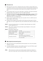
1. Before
Use
When the machine is delivered,
check for damage during transport
and missing parts. If any trouble is
found, inform the sales office
nearby.
When packaging of the machine and
holding fixture for transport are
attached to the body, be sure to
remove them before use.
Be sure to use NTN controller for
this machine.
Otherwise, specified performance of
the machine may not be obtained.
Introduction
・・・・・・・・・・・・・・・・・・・・・・・・・
1
1.
Before Use
・・・・・・・・・・・・・・・・・・・・・・・
1
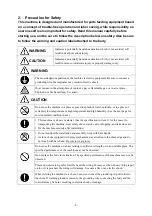
2.
Precaution for Safety
・・・・・・・・・・・・・
2
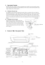
3.
Operating Principle
・・・・・・・・・・・・・・・
4
4.
Names of Main Component Parts
・・
4
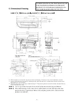
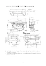
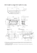
5.
Dimensional Drawing
・・・・・・・・・・・・・
5
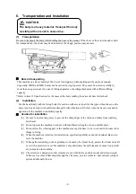
6.
Transportation and Installation
・・・・
8
7.
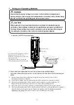
Wiring and Operating Methods
・・・・
9
8.
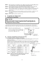
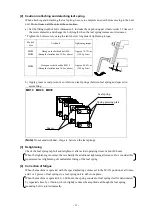
Inspection and Adjustment
・・・・・・・
10
9.
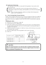
Fitting Work of Attachment
・・・・・・・
15
10.
Troubleshooting
・・・・・・・・・・・・・・・・・
16
11.
Specifications
・・・・・・・・・・・・・・・・・・・
17
Before use
Read this Instruction Manual
thoroughly, and operate the
machine correctly.
CONTENTS


