

- 4 -
3. Operating
Principle
NTN mono-drive 2-way feeder is a return type alignment feeder enabled to store, align and feed parts by
means of the alignment and feed side chute vibrated by the drive source of the feeder body and the return
trough vibrating in the direction opposite.
(1)
Vibrations of feeder body
The alignment and feed side chute installed on the upper vibrator is connected to the lower vibrator by
the leaf spring provided at a certain angle and they are vibrated with a magnet, so that works on the chute
are thrown upward aslant, resulting in little-by-little advancement of the works. As for vibration, large
vibration can be produced with small vibrating force by means of setting the strength of body leaf spring
properly corresponding to the installed chute mass and resonating by setting the absorption frequency of
magnet.
(2)
Vibrations of return trough
Leaf spring unit for return is installed on the lower
vibrator of the feeder body (1) above mentioned, works
can be advanced little by little to the opposite direction
by using vibration of the feeder body and transmitting
vibration of the different direction from that of aligning
and feeding side.
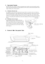
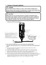
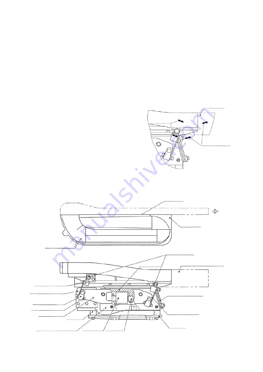
4.
Names of Main Component Parts
Upper vibrator
Chute mounting
area
Chute mount
Return trough
Return trough angle
adjusting screw
Counterweight
Magnet
Moving iron
core
Base
Work ejection
Chute
(Not included in the body)
Body / feed side leaf spring
Front and back
:
2 positions
Return side leaf spring
Front and back: 2 positions
Return mounting plate
(Cover)
Cushion
rubber
Mounting frame
Angle setting spacer
Lower leaf spring
mounting block
Upper leaf spring
mounting block
Chute part
Return vibrations
Body and feed vibrations


