

- 5 -
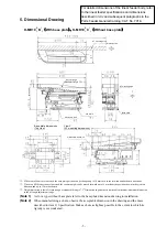
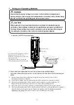
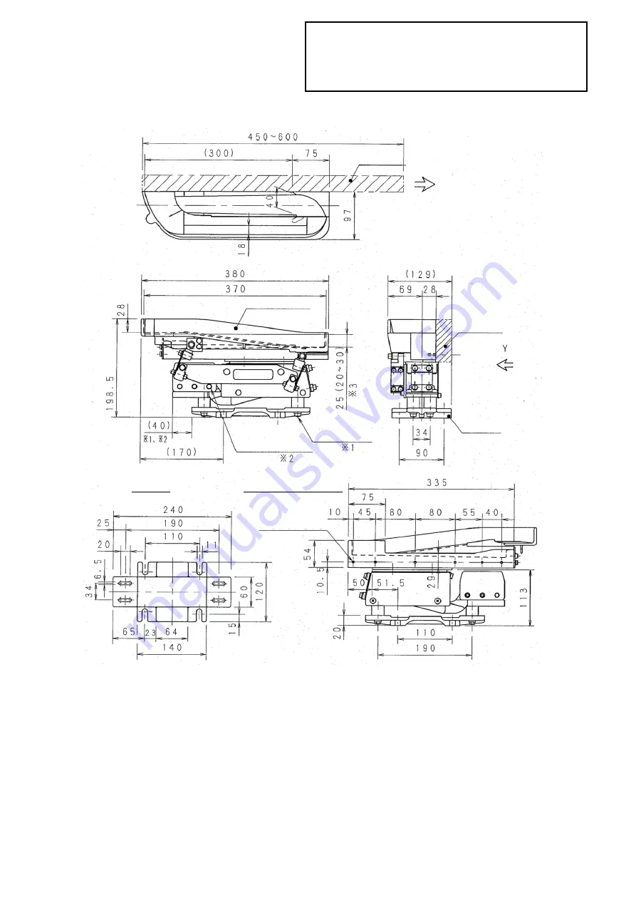
5. Dimensional Drawing
K-MD10
R
L
B
1
2
(
With base plate
)
、
K-MD10
R
L
C
1
2
(
Without base plate
)
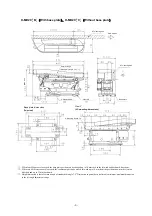
*1: When four M6 nuts are loosened, the base plate position can be changed up to 10 mm each in the forward and backward directions.
*2: When two M10 setscrews are loosened, the counterweight can be moved forward up to 15 mm from the position shown in the ejection
direction and up to 35 mm backward.
*3: Height dimension is that of return trough of standard tilt angle 7.5
0
. Dimension in parenthesis is alterable minimum/maximum dimension
in the tilt angle adjustment range.
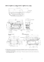
(Note 1)
As for a type without base plate refer to the base plate dimension drawing in installation.
(Note 2)
When manufacturing a chute, observe the acceptable dimension in the drawing and the mass
described in item 11 Specification. Make a chute as light as possible to the extent in which its
rigidity is not weakened.
For detailed dimensions of the linear feeder body, refer
to the linear feeder specifications and dimensions
described in
XI
/J and subsequent paragraphs in the
Parts Feeder General Catalog: CAT. No. 7018.
AT mounting area
Work ejection
(Standard tilt angle 7.5
°
±
1
°
)
(M
a
x. 189)
2-Setscrew M10
4-Nut M6
Base plate
Base plate dimensions
(Top view)
View Y
(AT mounting dimensions)
5-M5 screw, Depth: 15
AT mounting area
Return trough
(M
a
x. 205)


