

- 6 -
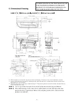
K-MD20
R
L
B
1
2
(
With base plate
)
、
K-MD20
R
L
C
1
2
(
Without base plate
)
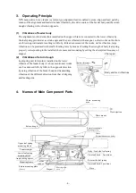
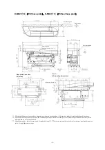
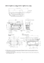
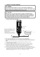
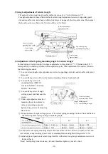
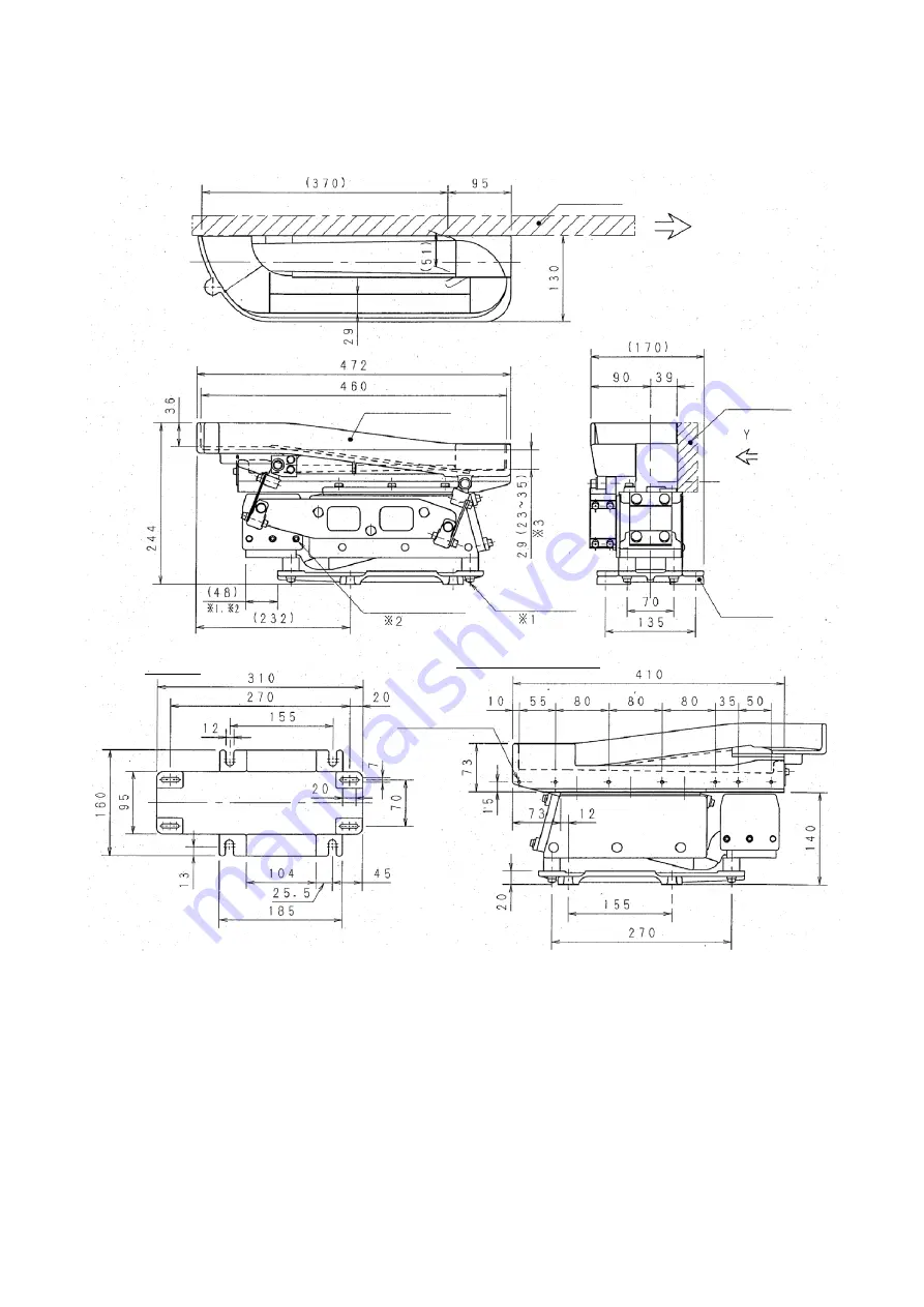
*1: When four M6 nuts are loosened, the base plate position can be changed up to 10 mm each in the forward and backward directions.
*2: When two M10 setscrews are loosened, the counterweight can be moved forward up to 10 mm from the position shown in the ejection
direction and up to 35 mm backward.
*3: Height dimension is that of return trough of standard tilt angle 7.5
0
. Dimension in parenthesis is alterable minimum/maximum dimension
in the tilt angle adjustment range.
AT mounting area
Work ejection
Return trough
(Standard tilt angle 7.5
°
±
1
°
)
(Ma
x.
2
5
1
)
2-Setscrew M10
4-Nut M6
Base plate
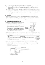
Base plate dimensions
(Top view)
View Y
(AT mounting dimensions)
6-M6 screw, Depth: 18
AT mounting area


