background image

- 9 - 

7. 

Wiring and Operating Methods 


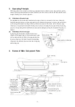
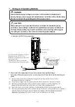
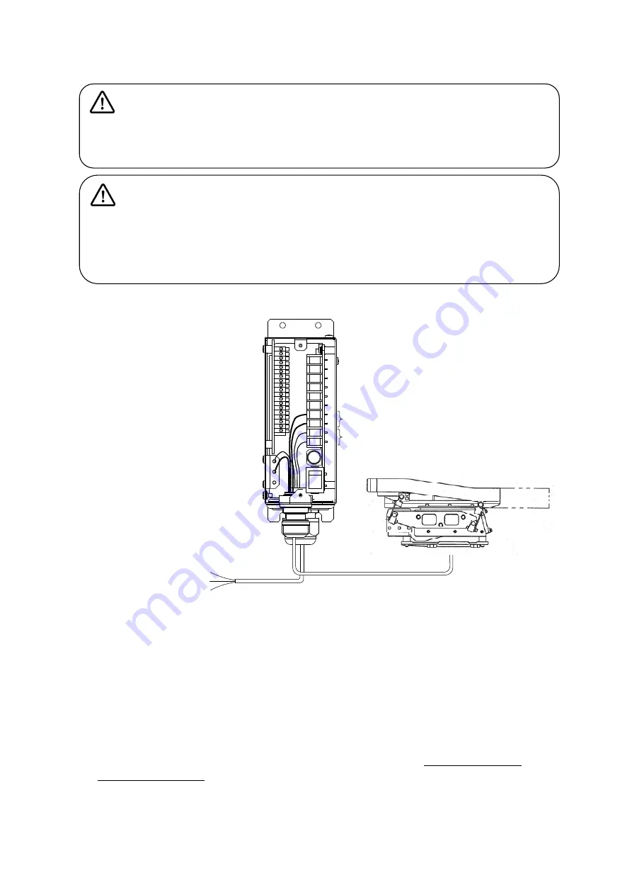
Controller (K-ECF25 as example) 


*1  Power cable to the single-phase AC power source (feeder body specified voltage). 

In the case of three-phase power source, use two phases out of three. Do not use the remaining one 
phase. 

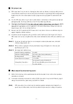
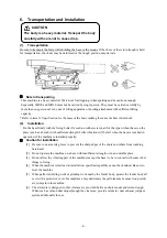
(1)  Remove transportation fixtures (Red tag) fixing the feeder body and the chute as well as 

transportation members, if attached. 

(2)  Connect power supply. (See the operation manual of the controller for connection in detail.) 
(3)  Turn the speed adjusting knob of the controller counterclockwise to set the graduation at "0". 

(Make sure that the feeder body is free and in no contact with something around.) 

(4)  Turn on the power switch of the controller. (Confirm lighting of LED on the operation panel.) 
(5)  Turn the speed adjusting knob of the controller slowly clockwise to set the graduation at a workpiece 

speed that matches with supply capacity. Operate this machine under the maximum acceptable 
amplitude of leaf spring in the item 8 in order to prevent breakage of leaf spring. 
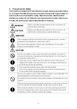
 

CAUTION 

When setting F-V curve and other data for a controller of variable frequency 

controllers, make settings conform to the specification and power conditions of 

the body. Wrong setting may result in accidents such as burning of the magnet. 

For setting for controllers, refer to the Controller Operation Manual. 


WARNING 

Ensure that the supply voltage is as shown on the machine nameplate (seal 

bearing the type, power supply and manufacturer’s serial No.) of the vibrator body. 

Be sure to connect the grounding wire of the power source. 

C2

EM

C1

AL1

Y1C

Y1A


It is connected to the single phase AC power. 

Please connect it to AC100-115V or 
AC200-230V according to the voltage of the 
main vibration body. 

  The frequency is both for 50 and 60Hz. 

  Connect green or green/ yellow to the earth. 

Power source 

Load(Parts feeder) 

Green

Red

White

Power cable 

Load cable 

*

Summary of Contents for K-MD10LB1

Page 1: ...the machine is delivered check for damage during transport and missing parts If any trouble is found inform the sales office nearby When packaging of the machine and holding fixture for transport are...

Page 2: ...n a place of extremely low temperature or high temperature and high humidity See the next page for environmental condition in use y This machine is a heavy material See the specification in item 11 fo...

Page 3: ...When noise level is above acceptable limit take a noise insulation measure with noise insulation cover etc Note 1 Do not use the machine when it is not in complete condition abnormal noise abnormal v...

Page 4: ...nding to the installed chute mass and resonating by setting the absorption frequency of magnet 2 Vibrations of return trough Leaf spring unit for return is installed on the lower vibrator of the feede...

Page 5: ...ment range Note 1 As for a type without base plate refer to the base plate dimension drawing in installation Note 2 When manufacturing a chute observe the acceptable dimension in the drawing and the m...

Page 6: ...rd up to 10 mm from the position shown in the ejection direction and up to 35 mm backward 3 Height dimension is that of return trough of standard tilt angle 7 50 Dimension in parenthesis is alterable...

Page 7: ...m from the position shown in the ejection direction and up to 65 mm backward 3 Height dimension is that of return trough of standard tilt angle 7 50 Dimension in parenthesis is alterable minimum maxim...

Page 8: ...when the base is touched in operation if the machine is installed properly Caution for installation 1 Be sure to wear safety gloves to prevent the sharp edges of the chute and others from touching bar...

Page 9: ...kpiece speed that matches with supply capacity Operate this machine under the maximum acceptable amplitude of leaf spring in the item 8 in order to prevent breakage of leaf spring CAUTION When setting...

Page 10: ...the fixing position of the counterweight is within the moving range shown in item 5 Dimension of 2 2 Inspection and adjustment of leaf spring of the body 1 Acceptable maximum amplitude of leaf spring...

Page 11: ...ly grease or rust preventive oil between leaf springs between leaf spring and spacer in assembling MD10 MD20 MD30 Note Do not sandwich dust chip etc between the leaf springs 3 Retightening Check the l...

Page 12: ...t from time to time and maintain an appropriate value Adjusting procedure 1 Remove the cover Allowed only on single side 2 Loosen the moving iron core tightening bolt 3 Insert a clearance gauge of the...

Page 13: ...ortation is possible Adjust number of leaf springs for the body feed side according to installed chute mass a Installed chute mass Target Number of body leaf springs Installed chute mass MD10 MD30 MD2...

Page 14: ...ng angle and tighten fixing screws of mounting frame to fix Mount number of angle setting spacers of lower leaf spring mounting blocks at front and back in the following table corresponding to mountin...

Page 15: ...r neutral detergent if it is found foul 9 Fitting Work of Attachment 1 The tilt angle of the return trough inclined surface can be adjusted by turning the angle adjusting screw shown in item 4 Names o...

Page 16: ...connected correctly as well as correct setting For details refer to the Controller Operation Manual d Magnet coil is not broken 2 Vibration is found although amplitude is insufficient 1 Imperfect pow...

Page 17: ...K PMG 211 1 1 piece K PMG 221 1 1 piece K PMG 321 1 piece Cable thickness x length from the center 1 0 mm2 1 1 m Body K PLS4 40 6 K PLS4 70 12 K PLS4 86 15 product number Return K PLS4 41 7 K PLS4 62...

Page 18: ...eturn feed track upper stream edge Feed side bottom face At time of 7 5 standard assembly 26 32 46 Applicable controller K ECF25 Frequency variable y The content of this instruction manual is subject...

Reviews: