background image

Contents 

How the NU-AIR System Works ........................................................................................................... 4 

Features and Operation ........................................................................................................................ 4 

Installation Instructions .......................................................................................................................... 4 

3.1 

Installer’s Responsibilities ............................................................................................................. 4 

3.2 

Installation Basics ......................................................................................................................... 4 

3.3 

Ductwork ....................................................................................................................................... 5 

3.4 

Weather Hoods ............................................................................................................................. 6 

3.5 

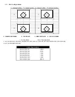
Port Configurations ....................................................................................................................... 7 

3.6 

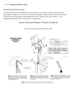
Mounting and Noise Control ......................................................................................................... 8 

3.7 

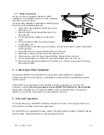
Drain Connections ....................................................................................................................... 10 

Connecting to Other Equipment .......................................................................................................... 10 

External Connections .......................................................................................................................... 10 

Unit Controls: Operation and Wiring ................................................................................................... 11 

6.1 

ES Series Controls (12 VDC) ...................................................................................................... 11 

6.1.1 

ES Control Wiring 

– applicable to all ES series controls .................................................... 13 

6.2 

Winsor Series & Other 24 VAC Control Options ......................................................................... 13 

6.2.1 

Terminal Designation/Function ........................................................................................... 13 

6.2.2 

Building Automation and Control Systems .......................................................................... 13 

6.2.3 

Standard Dehumidistat (Part # DSTAT-1) & 2-wire switches ............................................. 14 

6.2.4 

Windsor Control (Part # WIN-1) .......................................................................................... 14 

6.2.5 

Windsor Timer (WIN-20) ..................................................................................................... 14 

Control Board Status LEDs ................................................................................................................. 16 

Selectable Furnace/Air Handler Interlock ........................................................................................... 16 

8.1 

Furnace/Air Handler Interlock Wiring .......................................................................................... 17 

Defrost Operation ................................................................................................................................ 18 

10 

Balancing the System ..................................................................................................................... 19 

10.1 

Balancing Procedure: NU0103/NU305, NU0305/NU500, NU0406/NU600 ................................ 20 

10.2 

Balancing Procedure: NU0508/NU800, NU0912/NU1200, NU1316/NU1600 ............................ 21 

11 

Maintenance .................................................................................................................................... 21 

12 

Troubleshooting .............................................................................................................................. 23 

13 

Electrical Schematics ...................................................................................................................... 24 

14 

Warranty .......................................................................................................................................... 39 


Summary of Contents for NU0103

Page 1: ...due to ongoing product development and improvements For products using controller NU HRV Rev F manufactured April 2013 or later NU0103 NU0305 NU0406 NU0508 NU0912 NU1316 NU305 NU500 NU600 NU800 NU120...

Page 2: ...jury or damage to this product For indoor installations only If your H ERV is equipped with a 3 prong plug which will fit an A C electrical outlet in just one orientation Do not alter this plug or its...

Page 3: ...ontrols 13 6 2 Winsor Series Other 24 VAC Control Options 13 6 2 1 Terminal Designation Function 13 6 2 2 Building Automation and Control Systems 13 6 2 3 Standard Dehumidistat Part DSTAT 1 2 wire swi...

Page 4: ...s consist of two speed settings selectable from a remote control Connection between the HRV and control is achieved through low voltage wiring Features include Powerful transformer Intelligent defros...

Page 5: ...bows Joints should be tight fitting and sealed with high velocity fiber reinforced duct sealant or good quality duct tape RECOMMENDATION An engineer or other qualified person should design the duct sy...

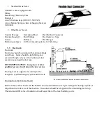
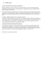
Page 6: ...ds the following Ventilation systems should be designed to prevent re entrainment of exhaust contaminants condensation or freeze ups and growth of microorganisms Make up air inlets and exhaust air out...

Page 7: ...3 NU0305 NU0608 NU0912 NU1316 NU305 NU500 NU800 NU1200 NU1600 A or E for NU0406 NU600 1 Outside Air OA 2 Supply Air SA 3 Return Air RA 4 Exhaust Air EA 1 4 1 3 A C 3 2 4 2 4 1 3 1 E G 2 3 2 4 Collar S...

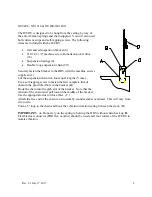
Page 8: ...from the ceiling by way of the anti vibration straps supplied Attach rubberized anti vibration straps with machine screws provided to the threaded brass insert in the top corners of the cabinet Avoid...

Page 9: ...chain into four equal lengths 5 max Use a self tapping screw to fasten the first complete link of chain to the pre drilled hole in the bracket B Hook the chain into the grab slot of the bracket Note t...

Page 10: ...se to form a P trap and terminate at the top of the tee 10 Pour water into the drain assembly to form an air seal This prevents gasses from being drawn into the HRV 4 Connecting to Other Equipment In...

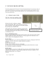
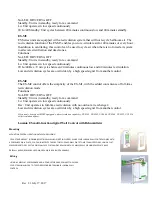
Page 11: ...h and select any function even if this interrupts a current mode or cycle ES T1 20 40 60 Minute Timer This timer is used to make the unit operate in high speed for 20 40 or 60 minutes and is typically...

Page 12: ...th the added convenience of full time recirculation mode Functions No LED HRV ERV is OFF Standby Unit is in standby ready for a command Lo Unit operates in low speed continuously Rec Unit operates in...

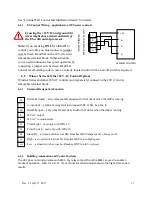
Page 13: ...s and other 24VAC controls sold separately connect to the 24V 10 wire removable terminal block 6 2 1 Terminal Designation Function Normally closed a dry relay contact paired with I that opens when the...

Page 14: ...1 Off 2 Standby 3 Continuous low speed 4 Intermittent high speed 5 Continuous high speed 6 2 3 Standard Dehumidistat Part DSTAT 1 2 wire switches The dehumidistat switches the HRV to high speed when...

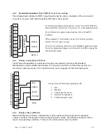
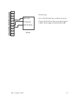
Page 15: ...BLE TERMINAL BLOCK NC I NO R C TL TS SB Hi LO PWR red LED yellow SWITCH black WIN 20 Win 20 Timer Up to 6 Win 20 timers may run off of one system If using only the Win 20 timer as a means of remote co...

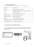
Page 16: ...STATUS NO LED UNIT TRANSFORMER IS NOT POWERED UNIT OFF Red is off Green is blinking slow every 1 s Also indicates processor is programmed and running STANDBY Green is OFF Red led is blinking slow ever...

Page 17: ...SYSTEM FURNACE 24 VAC NC I NO R C TL TS SB Hi LO UNIT 24 VAC REMOVABLE TERMINAL BLOCK THERMOSTAT TERMINALS Y R G W W G R C Y COOLING SYSTEM FURNACE 24 VAC STANDARD FURNACE INTERLOCK ALTERNATE FURNACE...

Page 18: ...The unit will resume normal operation for a fixed duration then the processor will read outdoor temperature and initiate defrost as necessary Defrost times and intervals will vary according to temper...

Page 19: ...flow It is recommended to use either a magnehelic gauge or a pitot tube air meter discussed here Depending on the device you are using follow one of the two procedures below Digital Manometer Pitot T...

Page 20: ...ERS ARE REQUIRED Be sure to close windows and doors and turn off all exhaust fans appliances during the balancing procedure High Speed Adjustment Balancing 1 Use any means to initiate high speed e g E...

Page 21: ...lyester filters should be vacuumed not washed and replaced annually Filters remove easily by opening the front cover Fans When cleaning the filters take the opportunity to vacuum any interior surfaces...

Page 22: ...ng than supply diffusers ANNUAL SERVICING Your H ERV should undergo annual general servicing by an accredited contractor This servicing should include the following The six maintenance items above A g...

Page 23: ...ines plugged HRV heat exchange core improperly installed Look for kinks in the line Check water drain connections Ensure that water drains from pan Poor air flow s HRV incorrectly balanced Filters nee...

Page 24: ...Schematics There are a number of configurations and options available for these products The schematic specific to your unit was supplied with the equipment The following pages illustrate typical gene...

Page 25: ...Rev 2 3 July 17 2017 25...

Page 26: ...Rev 2 3 July 17 2017 26...

Page 27: ...Rev 2 3 July 17 2017 27...

Page 28: ...Rev 2 3 July 17 2017 28...

Page 29: ...Rev 2 3 July 17 2017 29...

Page 30: ...Rev 2 3 July 17 2017 30...

Page 31: ...Rev 2 3 July 17 2017 31...

Page 32: ...Rev 2 3 July 17 2017 32...

Page 33: ...Rev 2 3 July 17 2017 33...

Page 34: ...Rev 2 3 July 17 2017 34...

Page 35: ...Rev 2 3 July 17 2017 35...

Page 36: ...Rev 2 3 July 17 2017 36...

Page 37: ...Rev 2 3 July 17 2017 37...

Page 38: ...Rev 2 3 July 17 2017 38...

Page 39: ...Recovery Ventilator HRV fails due to a defect in material or workmanship within fifteen 15 years NU AIR Ventilation Systems Inc will supply a new core FOB Factory to replace the defective part Deliver...

Page 40: ...indsor Nova Scotia 16 Nelson St P O Box 2758 B0N 2T0 Canada Ph 902 798 2261 Fax 902 798 2557 Email nuair nu airventilation com Web www nu airventilation com Email nuair nu airventilation com Website w...

Reviews: