background image

NITESTAR MODELS NS-50 AND NS-60

The Nu-Metrics NITESTAR Vehicle Installed Distance Measuring

Instruments are available in two models; the NS-50 and the NS-
60.  Both models are easy-to-use distance measuring instruments
(DMI) that facilitate land measurements from the convenience of
your automobile.  The model NS-50 includes features required for
most basic surveys and applications. 

The NS-60 includes all of the features of the NS-50 with the addi-

tion of a RS-232 Serial Port for connection of a serial printer, lap-
top computer, or GPS unit. With the RS-232 serial option and a
laptop computer, it is possible to conduct a complete highway
survey and then print directly to a 40 to 80 column serial printer.

DISTANCE MEASURING INSTRUMENT (DMI)

THEORY OF OPERATION

For electronic measurement of distance; a proximity sensor,

mechanical transmission sensor or electronic interface adapter is
used to provide speed pulses to the NITESTAR DMI for distance
measurements.  How the DMI calculates distance is relatively
simple for each of the sensors.

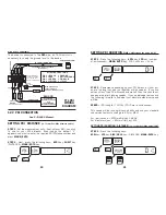
The proximity sensor divides the vehicle tire into pie sections by

equally spaced targets attached to the rim.  The spacing distance
between each target projects the proportional distance of the
outer circumference of the tire.  For illustrative purposes, assume
a 15 inch tire has an average rolling circumference of 7.16 feet.
The distance between targets is representative of one eighth of
the circumference, which in this example is 0.895 feet. This sen-
sor can also be mounted to make use of the drive shaft of a vehi-
cle and positioned to read the knuckles of the u-joint or a tar-
get(s) attached to the u-joint or the drive shaft.

The transmission sensor transmits six pulses for each revolution

of the internal disk.  Since most automobile speedometers are
based on 1000 revolutions per mile, approximately 6000 pulses
per mile are obtained. Dividing the pulses received (6000) into
the course length (5,280 feet) shows that each pulse represents
0.880 feet (5,280 divided by 6,000 = 0.880).

The electronic interface amplifier takes pulses already generat-

ed by the vehicle’s existing speed sensor and conditions this sig-
nal.  Most vehicle sensors generate more pulses than the DMI
needs so the electronic interface includes a divider circuit. This
circuit changes the 100,000 pulse/mile vehicle sensor pulse out-
put to the 6,000 per mile required by the DMI.

2

AUTOMATIC ERROR CORRECTION (AEC)

AEC is a software generated program that uses velocity and time
calculations to help compensate for errors from the sensor equip-
ment.  This is accomplished by constantly comparing the duration
of one sensor pulse to a subsequent pulse.  When a pulse is
missed, AEC will flash and the DMI will correct the count.  The
AEC will flash constantly on the left-hand side of the distance
screen when sporadic pulses are received, indicating that a prob-
lem exists and must be corrected.

INSTALLATION

NOTE: 

You may want to locate a garage or speedometer shop in your

area to perform the installation of the sensor and DMI instrument.

MOUNTING THE NITESTAR

The NITESTAR is designed to be mounted using the supplied
bracket or self-adhesive Velcro

®

strip fasteners that are provided

for direct mount. Determine the location where you will mount the
DMI in the vehicle.  This will assist in determining how to route
the power cable for the unit. The DMI should be angled so the
operator is able to see the display and keyboard. Remove the self-
adhesive protective covering from one of the Velcro fastener
strips. Place the sticky side down at the location where you are
locating the DMI. Remove the self-adhesive protective covering
from the matching strip and press firmly to the back of the DMI.
Mount the DMI to the first strip.  If using the bracket, repeat the
above procedures and fasten the DMI to the bracket before fol-
lowing the remaining steps.

– WARNING –

Do not mount a Nitestar in any area that may block the driver's
view or cause other obstructions.

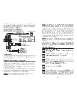
MOUNTING THE TERMINAL BLOCK - CAUTION!

All wiring and materials should be installed and routed as far
away as possible from spark plug wires, ignition coil wire, mani-
fold and exhaust pipes.  (Use the cable ties supplied with your
Installation Kit to secure wires away from these areas.)
Using the #6-32 screws from the installation kit, mount the ter-
minal block and electronic interface (if used) under the instru-
ment panel near the drivers seat. The fender well inside the
engine compartment on the driver’s side is an optional mounting
location.  If using the proximity sensor or mechanical transmis-
sion sensor, follow the directions provided with the sensor. Insert

3

Summary of Contents for NITESTAR

Page 1: ...or refers to proprietary information that is protected by copyright or patents Copying or other reproduction of this document and associated software for sale or distribution is prohibited without th...

Page 2: ...me 21 Setting PDI Duration Distance 21 Inside Front Cover Setting the Type of PDI 22 Low Going High PDI Output 22 High Going Low PDI Output 23 Flip Flop PDI Output 23 Advanced PDI Uses 24 Set Count In...

Page 3: ...I needs so the electronic interface includes a divider circuit This circuit changes the 100 000 pulse mile vehicle sensor pulse out put to the 6 000 per mile required by the DMI 2 AUTOMATIC ERROR CORR...

Page 4: ...OTE Depending on the terminal block location selected either the wiring harness from the DMI or the power cable from the battery will need to be routed through the vehicle firewall Usually this can be...

Page 5: ...6 same as MARK ENTER key Changes the SPEED units displayed each time the key is pressed Units Feet Second Miles Hour Kilos Hour See PDI Section See Access to Memory Programs Section See Memory Sectio...

Page 6: ...the fixed point 3 Press the RUN HOLD key 4 The display will show 8 5 Depress MARK ENTER The display will show 0 When the vehicle moves the display will show the pulses counted The value displayed is a...

Page 7: ...d a distance For example 99 intersecting street locations can be stored in memory with their corresponding dis tances These values are saved in the permanent memory so even after the unit is turned of...

Page 8: ...K value will go up by one and the code will become 00 again This would have stored a code 82 at distance 3216 in location number one 1 Now we are ready to enter location two 2 You can continue in this...

Page 9: ...K ENTER to store data in memory a line will print showing this data on the printer See the RS 232 PRINTER section for further details 14 PRINTING MEMORY If you have the RS 232 option and a printer you...

Page 10: ...ght Centerline Markings 16 PASS B Pass Both Ways 17 PASS L Pass Left 18 N PASS No Passing Both Ways 19 DRW Driveway 20 M B Mailbox By default the NITESTAR prints the memory transfer as shown above wit...

Page 11: ...r tracks all visible GPS satellites continuously and uses all the measurements obtained to produce a GPS navigation solu tion Position jumps caused by blockage in receivers with fewer chan nels are gr...

Page 12: ...RED BLACK ELECTRONIC INTERFACE SENSOR or the TRANSMISSION INTERFACE SENSOR SENSOR TO TTL DEVICE Jump to Black to Battery BLACK WHITE BLACK RED RED CABLE FRONT VIEW 1 2 3 4 TTL PDI WIRING DIAGRAM SETTI...

Page 13: ...pulse will go on then never shut off SETTING THE TYPE OF PDI The device that uses the PDI signal sometimes has certain requirements for the signal The NITESTAR can produce three types of PDI Let us ta...

Page 14: ...in the INTERVAL window SUMMARY PDI KEYS First Press 8PDI and then 2 Set PDI Distance 3 Set PDI Duration by TIME 3 Set PDI Duration by DISTANCE DISP HOLD 4 Set Flip Flop PDI High then low on alternate...

Page 15: ...E After you press the 2 UNIT key the default 1 will appear At this time re enter the value of unit measurement need ed Then press MARK ENTER key SET COUNT INCREMENT The Count Increment number is the a...

Page 16: ...he instrument in COUNT HOLD mode set the desired speed and distance units 2 Press PRM 6 MARK ENTR to enter the speed trap program 3 Display will show COURSE Enter in the distance between the mark ers...

Page 17: ...AGE CALCULATION NS 50 60 This is used to estimate the amount of material for a project the vol ume is calculated as in PRM 11 and then is multiplied by lb cu yd or kg cu m This yields an estimate of t...

Page 18: ...them down On a Model 60 the values can be printed on a DPU 411 or captured on a computer STEP 6 When you are done go to COUNT HOLD using the RUN HOLD key Then press CLEAR to exit TSD mode Use PRM30 M...

Page 19: ...hicle to obtain a real time printout or in the office to dump inventory data previously stored in the Nitestar s Memory Remember to fully charge your printer before starting your sur vey turn off the...

Page 20: ...50g PAPER Jujo Paper Co TP411 28CL Paper width 112 mm roll diameter 48mm roll length 28m OPERATING CONDITIONS 1 Operating temperature and humidity 0 40 C 30 85 RH 2 Storage temperature and humidity 20...

Page 21: ...with your Name Address Both street and P O Box and a tele phone number so that we can contact you if necessary 38 LIMITED WARRANTY The Nu Metrics Nitestar instruments are covered by a one year limite...

Page 22: ...ection and then you will only have to click the connection Icon to use it again SETTING UP HYPERTERMINAL From the START menu 40 Double click on HYPERTERMINAL you will get The program will start and yo...

Page 23: ...Pick that to start the program the next time 43 Use the serial I O parameters shown below The next step is to set it so that when you look at data from the NS 60 it will display correctly on the scre...

Page 24: ...unt up or down PDI Count Display TTL Output 12 VDC 1 Amp with P N 1050 DIMENSIONS 7 5 190 5mm x 2 25 57 15mm x 88 22 5mm CALIBRATION Auto Calibration Entry Manual WEIGHT 7 0 oz UNIT Auto conversion Ft...

Page 25: ..._______ Purchase Date ________________ Your Name ___________________ Phone _______ __________________________________________ Your Shipping Address ____________________________________________________...

Page 26: ...ft 7587 1814 29 Passing Allowed 39 56 03 7560 N 79 38 37 6980 W 1226ft 8201 614 31 No Pass Zone 39 55 57 6900 N 79 38 38 7780 W 1266 ft 8697 496 8 Stop Sign 39 55 52 1160 N 79 38 38 6580 W 1265 ft 101...

Reviews: