background image

14

E

.0

4.

20

00

 •

 G

. 1

6.

11

.1

0

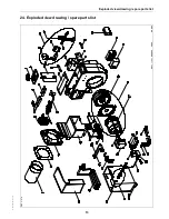
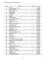
Exploded view drawing / spare parts list

Position

Designation

Pack qty.

Art. No.

1

Burner pipe

1

47-90-27900

2

Diaphragm plate compl. with holder

1

47-90-27885

3

Nozzle assembly compl.

1

37-90-11304

4

Delavan HV1.5 nozzle

1

59-10-50448

5

Ignition electrodes (left + right)

1

47-90-26037

6

Ignition cable G55

1

47-90-27621

7

Air control handwheel

1

47-90-12100

8

Air damper flange

1

47-90-12099

9

Air damper compl. 

1

47-90-12096

10

Housing cover

5

47-90-12095

11

Sight glass

5

47-50-12105

12

Sight glass cover

5

47-50-12106

13

7-pin socket with cable

1

47-90-11839

14

Control unit bottom part S98 9-pin. compl.

1

31-90-22664

15

Satronic TF 834.3 control unit

1

37-90-11285

16

Fan wheel 146 x 52

1

47-90-12104

17

Motor 180 W

1

47-90-12113

18

Motor with fan impeller compl.

1

47-90-27249

19

Coupling

10

37-50-10110

20

Suntec D45B pump with connections

1

47-90-26160

21

Conical nipple AL 13 x 18 x 2

50

38-50-11293

22

Hose nipple R 1/4“ x 8LL

10

37-50-11348

23

Metal hose, nom. size 6

1

47-90-11347

24

Pump - solenoid valve connecting tube

1

37-90-10780

25

Banjo screw R1/8“

10

37-50-10736

26

Conical nipple AL 14 x 10 x 2

50

37-50-10788

27

Solenoid valve R1/4“ SV04

1

36-90-11583

27

Solenoid valve coil

1

47-90-24686

28

Thread reducing adaptor 1/4“ - 1/8“

1

47-90-11303

29

Solenoid valve - oil tank connecting tube

1

47-90-26171

30

Oil tank connection compl.

1

47-90-27627

31

Seal 24 x 16 x 2

10

47-50-10516

32

Drain valve

1

47-90-10472

33

Intake tube compl.

1

47-90-24514

34

Heating coil 1100 W

1

47-90-24505

35

Oil tank G100 compl.

1

47-90-26177

36

Oil tank cover

1

47-90-24520

37a

Oil tank - nozzle assembly connecting tube part 1

1

37-90-10370

37b

Oil tank - nozzle assembly connecting tube part 2

1

37-90-10371

38

Control housing shroud, compl. preassembled

1

47-90-27351

39

Safety thermostat

1

47-90-27327

40

Flush-type thermostat

1

47-90-22805-01

41

Twin microswitch

1

47-90-10601

42

Float

1

47-90-22420

43

Control housing cover

1

47-90-24525

44

Electronic ignition unit Mod. 26/48

1

47-90-26930

45

Flame detector MZ770 compl. with cable

1

47-90-22816

46

Swivel flange compl.

1

47-90-26181

47

Mounting flange seal

5

47-50-24429

48

Air distributor connecting tube

1

47-30-27631

49

Air distributor, compl. preassembled

1

47-90-24568

50

Safety valve

1

47-90-26640

51

Pressure gauge 0-2.5 bar

1

47-90-12121

52

Solenoid valve coil

1

59-90-50368

53

Double reduction nipple 1/4“ - 1/8“

1

44-90-23075

54

Replacement pressure regulator

1

47-90-24594

Summary of Contents for G100 Universal

Page 1: ...G100 Universal Oil Burner Installation Maintenance Manual...

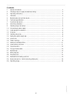
Page 2: ...ge and burner 5 10 Connecting to power supply 5 11 Compressed air connection 5 12 Oil pump 6 13 Installing the oil line 6 14 Setting the ignition electrodes 6 15 Control unit 7 16 Table of settings 8...

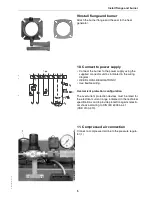
Page 3: ...mounting unit separate operating instructions technical information flange seal Near wear free compressed air atomising nozzles are pre fitted at the factory 3 Operating instructions This technical i...

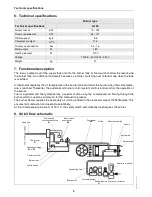
Page 4: ...mbustion process The burner blower supplies the secondary air which is added to the atomised spray at the baffle plate This ensures full combustion and operational reliability At the oil temperature i...

Page 5: ...it as indicated in the wiring diagram HEED LOCAL REGULATIONS Use flexible wiring Overcurrent protection configuration The overcurrent protection devices must be rated for the electrical current range...

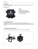
Page 6: ...adjustment 13 Installing the oil line Install oil lines filters and floating suction unit from the supply pump to the supply tank For installation in the open air or on outside walls the lines must b...

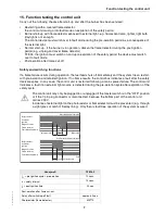
Page 7: ...llowing a mains power failure The control unit indicates a fault if an external light source is detected during the pre aeration cycle after expiration of the safety cycle The control unit may only be...

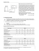
Page 8: ...deviate Adjustment is required in any case due to the system design For initial start up fill the burner tank up to the oil mark by hand Caution If the oil level is too high the float switch will swi...

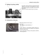
Page 9: ...an be used as guide values Higher viscosity fuels require higher air pressures 18 Combustion air flow rate Setting the combustion air flow rate 2 Ideal values Soot index according to Bacharach 1 O2 4...

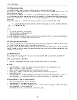
Page 10: ...a flue gas thermometer The higher the flue gas temperature the greater the flue gas loss Rising flue gas temperatures indicate increasing deposits that will reduce the degree of combustion effi cienc...

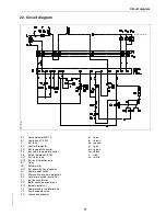
Page 11: ...thermostat STB H11 Ext status lamp H13 Ext fault indication lamp K1 Relay M1 Burner motor P11 Ext operating hours counter Q1 Heater power switch S1 Micro switch overflow protection S2 Level micro swit...

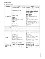
Page 12: ...in burner tank encrusted or faulty Clean or replace the heating cartridge and thermocouple in the burner tank Burner starts without pre ventilating Solenoid valve sticking in open position Replace No...

Page 13: ...13 E 04 2000 G 16 11 10 Exploded view drawing spare parts list 24 Exploded view drawing spare parts list ZBZ_2 278...

Page 14: ...4 x 10 x 2 50 37 50 10788 27 Solenoid valve R1 4 SV04 1 36 90 11583 27 Solenoid valve coil 1 47 90 24686 28 Thread reducing adaptor 1 4 1 8 1 47 90 11303 29 Solenoid valve oil tank connecting tube 1 4...

Page 15: ......

Page 16: ...G100 Universal Oil Burner 07 11 Enertech Limited P O Box 1 Vines Lane Droitwich Worcestershire WR9 8NA tel 44 0 1905 794331 fax 44 0 1905 794017 email info nu way co uk web www nu way co uk...

Reviews: