AIR ADJUSTMENT
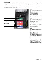
The damper motor turns the damper between 3 preset positions: These positions are controlled in the motor by cams which
are set by means of the coloured disks. In addition there is a black disk controlling the connection of solenoid valve 2 and a
green disc controlling the connection of solenoid valve 3.
If the air volume needs changing: Remove the cover from the damper motor and change the position of the cams by turning
them with the tools accompanying the burner.
Stage 1:
Adjust the operating switch to stage 2
(II).
* Reduce the air volume:
Turn blue cam towards 0°.
* Increase the air volume:
Turn blue cam towards 90°.
Adjust the operating switch back to
stage 1 and check.
Stage 2:
Adjust the operating switch to stage 1
(I).
* Reduce the air volume:
Turn orange cam towards 0°.
* Increase the air volume:
Turn orange cam towards 90°.
Adjust the operating switch back to
stage 2 and ensure that the correct air
volume has been obtained.
Stage 3:
Adjust the operating switch to stage 2
(II).
* Reduce the air volume:
Turn red cam towards 0°.
* Increase the air volume:
Turn red cam towards 90°.
Adjust the operating switch to stage 3
(III) and ensure that the correct air volume
has been obtained.
NOTE
On adjustment of stage 2 and stage 3
the black cam (Mv2) must be within the
settings of the blue and orange cams
and the green cam (Mv3) within the
settings of the orange and the red cams.
Solenoid valve stage 3 (green)
Solenoid valve stage 2 (black)
Stage 3 (red)
Stage 2 (orange)
Stage 1(blue)
171 305 92 00-01
Summary of Contents for MOL 1650-3R B70 2-3
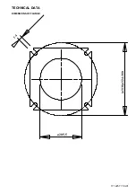
Page 4: ...TECHNICAL DATA DIMENSIONS OF FLANGE 171 225 77 00 01 14 310 324 380 205 5...
Page 14: ......
Page 16: ...NOTES...
Page 17: ...NOTES...


