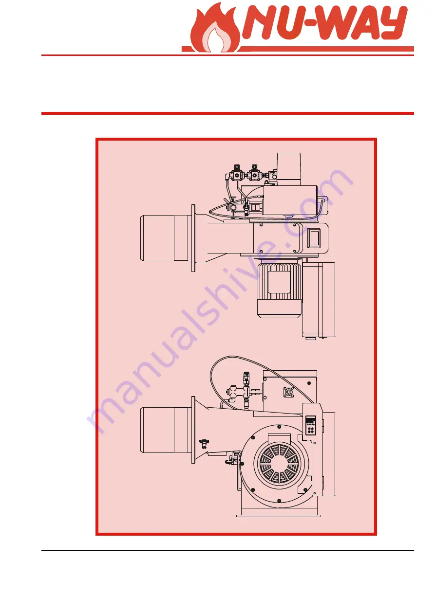
background image

Page 1

NOL Compact Modulating

H

ANDBOOK

Series NOL fully automatic oil burner

Models NOL Compact Modulating

Class D Oil

®

Summary of Contents for NOL

Page 1: ...Page 1 NOL Compact Modulating HANDBOOK Series NOL fully automatic oil burner Models NOL Compact Modulating Class D Oil ...

Page 2: ...ents 6 Plant Room Ventilation 6 Existing Appliances 7 Combustion Chamber Conditions 7 INSTALLATION 7 General 7 Fitting to the Appliance 7 Oil Supply Connections 7 Electrical Power Connection 7 BURNER AIR CONTROLS 7 Air Diffuser 7 BURNER OIL CONTROLS 7 Oil Nozzle 7 Oil Control Train 7 Modulating Unit 7 BURNER OIL SYSTEM 8 ELECTRICAL CONNECTIONS 9 OPERATION 10 COMMISSIONING 10 IMPORTANT SAFETY 10 EM...

Page 3: ...res average water temperature and CO2 or O2 concentration ROUTINE MAINTENANCE OF NOL MODULATING BURNERS 13 General 13 Daily Checks 14 Photoelectric Cell 14 Replenishing the Fuel Supply 14 Boiler Combustion Surface 14 FAULT FINDING 14 If the Burner Fails to Start 14 If the burner is found at lockout red lockout lamp illuminated 14 Flame Occurs Followed by Immediate Lockout 14 The Burner Starts With...

Page 4: ...NOL Compact Modulating Page 4 BURNER COMPONENT IDENTIFICATION Standard Burner Arrangement Shown All dimensions are mm 851 5 352 7 21 ...

Page 5: ... 4 7 6 0 3 4 7 5 4 7 5 4 7 8 3 0 4 4 4 5 2 5 0 3 8 3 0 5 L O N 5 6 4 1 2 7 0 3 4 0 8 4 0 8 4 0 8 4 4 5 2 5 0 3 8 2 0 6 L O N 0 4 4 4 7 6 0 3 4 7 5 4 7 5 4 7 8 3 0 4 4 4 5 2 5 0 3 4 3 0 6 L O N 0 4 4 4 7 6 0 3 4 0 8 4 0 8 4 7 8 3 0 4 4 4 5 2 5 0 3 8 3 0 6 L O N 5 6 4 1 2 7 0 3 4 0 8 4 0 8 4 0 8 4 4 5 2 5 0 3 8 3 5 8 L O N 5 6 4 1 2 7 0 3 4 7 3 5 0 8 4 0 8 4 0 8 2 5 0 3 M E T I N O I T P I R C S E D...

Page 6: ... complete the manual Literature on proprietary components is available on request SITE CONDITIONS AND SERVICES Fuel Storage and Handling The requirements of BS2869 will ensure that the fuel is suitable Under sustained cold and exposed conditions class D grade of fuel should be stored and supplied to the burner at a minimum temperature of 5 C 41 F Fuel Supply The oil line should consist of metallic...

Page 7: ...facturers instructions BURNER AIR CONTROLS A motorised cable driven air flap controls the air for combustion It is located inside the air inlet Air Diffuser The air diffuser creates a pressure drop to ensure good fuel air mixing and flame stability BURNER OIL CONTROLS Oil Nozzle The oil nozzle is of the spill back type and is fitted to the front end of the inner assembly and located in the flame t...

Page 8: ... 77 M E T I N O I T P I R C S E D 1 h c t i w S e r u s s e r P 2 e v l a V l o r t n o C l l i p S 3 e v l a v k c e h c n r u t e R n o N 4 e g u a G e r u s s e r P d e e F 5 e g u a G e r u s s e r P l l i p S 6 e v l a V f f O t u h S e g u a G 7 k c o l B d l o f i n a M r e n r u B 8 d e e F e v l a V y t e f a S C N 9 n r u t e R e v l a V y t e f a S C N 0 1 p m u P l i O 1 1 e l z z o N ...

Page 9: ...6833 1 3 6 86 62 7 6833 7 7 K 7 7 7 7 3 1 32 5 7 51 211 7 216 9 3 1 3 8 6 32 5 7 51 211 7 216 9 851 5 7 50 1 675 3 237 21 5 029 3 1 3 8 6 ELECTRICAL CONNECTIONS M E T I N O I T P I R C S E D 2 F t n e m u r t s n I t i m i L e c n a i l p p A 1 H l a n g i S t l u a F r e n r u B 2 H l a n g i S g n i t a r e p O r e n r u B 1 N t n e m u r t s n I f f O n O e c n a i l p p A 1 P n u R s r u o H g...

Page 10: ...l burner commissioning Nu way can accept no responsibility for consequential loss damage or personal injury which results from a failure to follow the commissioning instructions provided or from commissioning procedures being undertaken by unqualified personnel EMERGENCY INSTRUCTIONS NOL Modulating burners are designed and constructed to meet current legislation When used in accordance with the in...

Page 11: ...id on the modulating cam box unit Switch on the burner at the control panel The modulating unit camshaft should now rotate to the high flame setting and the combustion air motor will start the air pre purge phase Allow the fan motor to run up to speed switch off the burner and check the fan rotation Anti clockwise as viewed from the motor side as the fan slows down Remove and cover the photoelectr...

Page 12: ... Plunger Locking Screws Profile Band Cam Lever Operating Cable Adjuster Locking Screws Profile Adjuster Retaining Saddle Cable Adjuster Oil Cam A Air Cam B Oil Cam View On A Air Cam View On B View of Servomotor from underside cover removed showing position of disengagement lever Rotation for High Flame position Cams shown in the Low Flame Position Fig 1 Fig 2 Spill Pressure Reduce Increase ...

Page 13: ...oil flow Continue to repeat a to d until the high flame oil rate is correct When a satisfactory flame is achieved again check the line and spill pressures Inch the camshaft back to the low flame position The oil consumption rate should now be between 35 and 50 of the rated maximum Measure the flue gas composition and adjust the combustion air volume as necessary Check the burner performance throug...

Page 14: ...d before proceeding further On steam boilers check that the water level interlocks are in the made position If the burner is found at lockout red lockout lamp illuminated Reset the burner and observe the starting sequence Make reference to the Sequence Diagram and Timing Charts for the Flame Failure controls on page 15 for further information Check the fan motor overload and reset if necessary Fla...

Page 15: ...he lockout window should also be noted prior to resetting the burner Refer to theSequence Diagram and Timing Chart below PLEASE NOTE When the control box goes to lockout it is generally performing the function it is designed for Burner Control Program Burner operational sequence based on the Landis staefa LAL1 25 Control box Note Timings are for operation on a 50 hz electrical supply only D O I R ...

Page 16: ...lled shut down or after each mains failure the se quence switch always runs through to the start position whereby only terminals 7 9 10 and 11 receive voltage in accordance with the control pro gram It is only then that the control unit programs a fresh burner start up Note Do not press the lockout reset button or remote reset switch for more than 10 seconds RWF40 MODULATING CONTROL Basic display ...

Page 17: ...ted range of that parameter All other parametrs must remain as supplied Note The detector range parameters SCL SCH are given as C for Hot Water temperature and bar for Steam pressure F W R 0 4 RECOMMENDED SETTINGS r e t e m a r a P y a l p s i D t o H r e t a W m a e t S l a n o i t r o p o r P d n a b 1 b P 0 1 1 e v i t a v i r e D e m i t t D 0 1 5 e m i t t e s e R t R 0 5 0 2 r o t a u t c A ...

Page 18: ...handbook Should it become necessary to order replacement parts it is important to quote the burner model specification and serial numbers to ensure correct expedition of your order Nu way Ltd is able to offer on site Commissioning Service and Repair through its wordwide network of authorised distributors and sales offices Please contact the Nu way Service Department for further information BURNER ...

Page 19: ...TPUT Kg h 0 5 10 15 20 TOTAL RESISTANCE mbar 50 100 150 200 240 NOL18 38 NOL18 34 NOL35 34 NOL35 38 NOL30 25 NOL50 38 NOL60 38 NOL85 38 NOL100 38 NOL50 28 NOL50 34 NOL60 34 NOL60 NOL35 25 28 Burner outputs are based on a gross calorific value of class D fuel of 12 66 kW Kg Graphs produced in accordance with BS EN 267 ...

Page 20: ...R r o t c i r t s e R 1 1 e l z z o N l i O R E N R U B A Ø B Ø C Ø D Ø R E N R U B A Ø B Ø C Ø D Ø 4 3 8 1 L O N 8 7 1 5 6 1 2 5 1 5 6 1 8 2 0 5 L O N 0 2 2 7 9 1 8 7 1 6 0 2 8 3 8 1 L O N 8 7 1 5 6 1 2 5 1 5 6 1 4 3 0 5 L O N 0 2 2 7 9 1 8 7 1 6 0 2 5 2 0 3 L O N 8 7 1 5 6 1 2 5 1 E N O N 8 3 0 5 L O N 0 2 2 7 9 1 8 7 1 6 0 2 5 2 5 3 L O N 8 7 1 5 6 1 0 4 1 E N O N 8 2 0 6 L O N 0 2 2 7 9 1 8 7 ...

Page 21: ...8 2 0 3 5 3 6 6 0 2 5 1 5 2 0 3 L O N 0 0 8 2 5 1 7 1 6 3 6 1 5 1 5 2 5 3 L O N 0 0 8 2 5 1 7 1 6 3 6 1 5 1 4 3 5 3 L O N 0 0 8 2 0 3 5 3 6 6 0 2 5 2 8 3 5 3 L O N 0 0 8 2 0 4 5 4 5 8 5 2 5 2 8 2 0 5 L O N 0 0 8 2 0 3 5 3 6 6 0 2 5 2 4 3 0 5 L O N 0 0 8 2 0 4 5 4 5 8 5 2 5 2 8 3 0 5 L O N 0 0 8 2 5 5 7 5 3 1 1 2 3 5 2 8 2 0 6 L O N 0 0 8 2 0 4 5 4 5 8 5 2 5 2 4 3 0 6 L O N 0 0 8 2 0 4 5 4 5 8 5 2 ...

Page 22: ...__________ Rating ________________ Spec No ______________ Serial No _______________ Nozzles ______________ Oil Pump _____________ Commissioning date __________________ Guarantee Expiry Date ________________________ Oil type ____________________________ s l i a t e D n o i t s u b m o C w o L e m a l F t n i o P 2 t n i o P 3 t n i o P 4 t n i o P 5 h g i H e m a l F O C 2 N e k o m S O C p m e T t...

Page 23: ... g n i c i v r e S e h t y b d e t e l p m o c e b o t e r a w o l e b s l i a t e d e h T t n e m t s u j d a e c i v r e s h c a e g n i w o l l o f d e n g i s d n a d e t e l p m o c e b o t t e e h s s i h T e t a D e c i v r e S f O s l i a t e D e r u t a n g i S ...

Page 24: ... WAY LIMITED P O Box 1 Vines Lane Droitwich Worc WR9 8NA England Telephone 01905 794331 e mail info nu way co uk Fax Office 01905 794017 Parts Components 01905 795829 NOL Modulating PM65 Revision 101201B BS EN ISO 9001 CERT No FM00921 ...

Reviews: